MV-9_Chapter 5. Teaching.pdf - 第216页
MV -9 Use r Manual 5- 216 [Figure 5- 275 Center of binary inspection-componen t search inspection setting and preview image] - Center Point : position of hole center in i nspect io n w i ndow . - Circle Radius : radius o…
错误!使用“开始”选项卡将 제목 2 应用于要在此处显示的文字。错误!使用“开始”选项卡将 제목 2 应用
于要在此处显示的文字。 .
5-215
- Position compensation function is used for mounting inspection.
[Figure 5-274 teaching example]
② Reference point (mark) teaching and setting
- Center position of LED package is relative position for center position of circle reference
point.
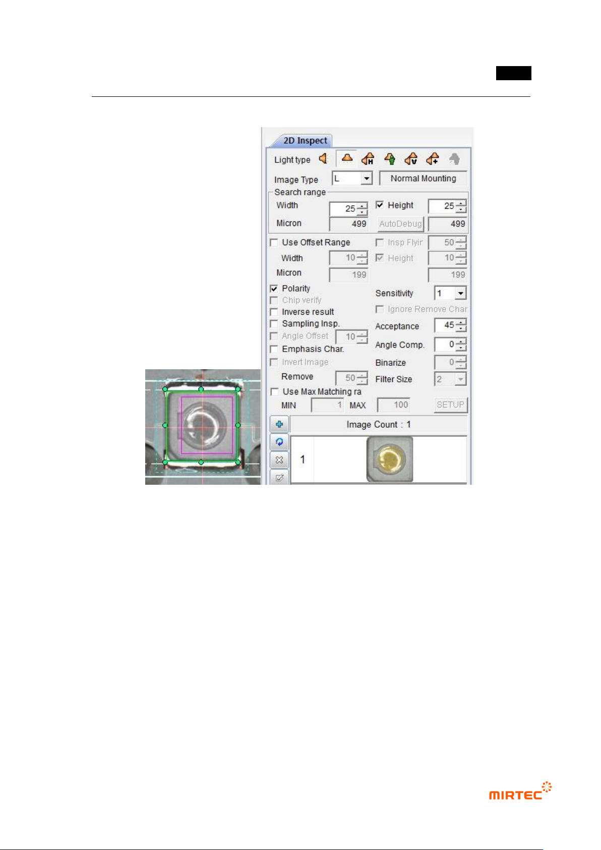
- Create binary inspection window to detect center position of reference point, select
component center search, and select circle for figure type.
- Check at „Use Subpixel‟. If Cognex license key is installed, check at „Use Cognex‟.
- Select preview, and adjust binarization for proper separation of edge of reference point.
- Conduct trial inspection to display center position of reference point at current central point
in inspection window. After normally calculating center, click reference central point
registration.
- Set tolerance range as big as possible. (Reference: reference point is used as criteria to
inspect X/Y-shift of LED package during BLU inspection. Hence, tolerance range is
meaningless.)
MV-9 User Manual
5-216
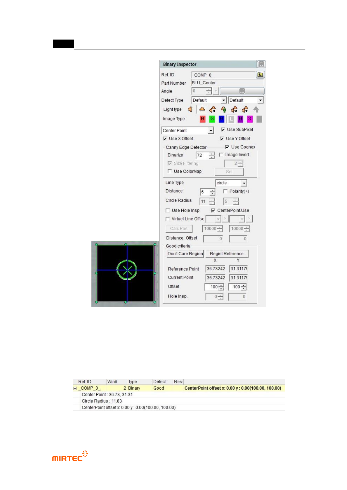
[Figure 5-275 Center of binary inspection-component search inspection setting and preview image]
- Center Point: position of hole center in inspection window.
- Circle Radius: radius of detected circle.
- CenterPoint Offset x, y: difference between reference central point and current central
point.
[Figure 5-276 center of binary inspection-component search result]

错误!使用“开始”选项卡将 제목 2 应用于要在此处显示的文字。错误!使用“开始”选项卡将 제목 2 应用
于要在此处显示的文字。 .
5-217
③ Teaching and setting center of LED package component search
- Create binary inspection window to detect Center position of LED package, select
component center search, and select horizontal and vertical light for light type.
- Check at „Use Subpixel‟. In case Cognex license key is installed, check at „Use Cognex‟.
- Select LED circle for detection type.
- Select preview, and adjust binarization for proper edge separation.
- Check at „Polarity (+)‟. This means that edge that changes from black area to white area is
found. (Reference: center position of fluorescent substance will be calculated by circle
fitting and conducted in gray image. segment total area into area of specific area, and find
edge for each segmented area in exterior of inspection area toward center direction. Edge
detection principle is same with binary inspection-position move.)
- Check at „virtual line offset‟ and register reference point. Select reference point used to
calculate Position of LED package first, and select opposite reference point as the second.
(Reference: This is to match central point of LED package and position calculation method
for central point of lens. register reference point of direction to which connector is mounted
as the first reference point in BLU bar.)
- Conduct trial inspection to display (unit pixel) center position of reference point at the
current central point in inspection window. Normally, click reference central point
registration after calculating center.
- Click position calculation, and enter distance X value from the first reference point to LED
package and horizontal line that links 2 reference points and vertical distance (unit um) Y
value of center of LED package. Refer to Result Center Point (X/Y) value of inspection
result.
- Enter Circle Radius value and allowable range of inspection UI (unit pixel) referring to
Circle Radius in inspection result.
- Distance Offset can be entered only in agent mode, and enter it after measuring using
master sample board (unit um). Define average difference measurement data of X/Y
coordinate of center position of LED package and master data as Distance Offset. If there
are more than 2 LED packages in 1 frame, calculate each Distance Offset and enter it.
- Enter value to judge normal / defect (unit um) for tolerance range.