MV-9_Chapter 5. Teaching.pdf - 第224页
MV -9 Use r Manual 5- 224 This function is used when co m ponent o f base m odu le is d i ffere nt fr om confi guration or used for teaching for 90° rotated m odul e. [Figure 5- 289 Example of new module creation functio…
错误!使用“开始”选项卡将 제목 2 应用于要在此处显示的文字。错误!使用“开始”选项卡将 제목 2 应用
于要在此处显示的文字。 .
5-223
[Figure 5-287 hierarchy structure of inspection window]
module add
To reduce teaching and debugging time during connecting module substrate teaching, use this
function to equally apply teaching for base module to other modules.
[Figure 5-288 new module creation]
Caution
To add module, teaching of compensation mark of base module must be
conducted. If there is no compensation mark on base module, compensation
mark window must be created at specific area that has same function with
compensation mark.
new module creation
PCB Model
Module
Part
Inspection
window
Inspection
window
Part
Inspection
window
Inspection
window
Inspection
window
Inspection
window
Module
Part
Inspection
window
Inspection
window
Part
Inspection
window
Inspection
window
Inspection
window
Inspection
window
MV-9 User Manual
5-224
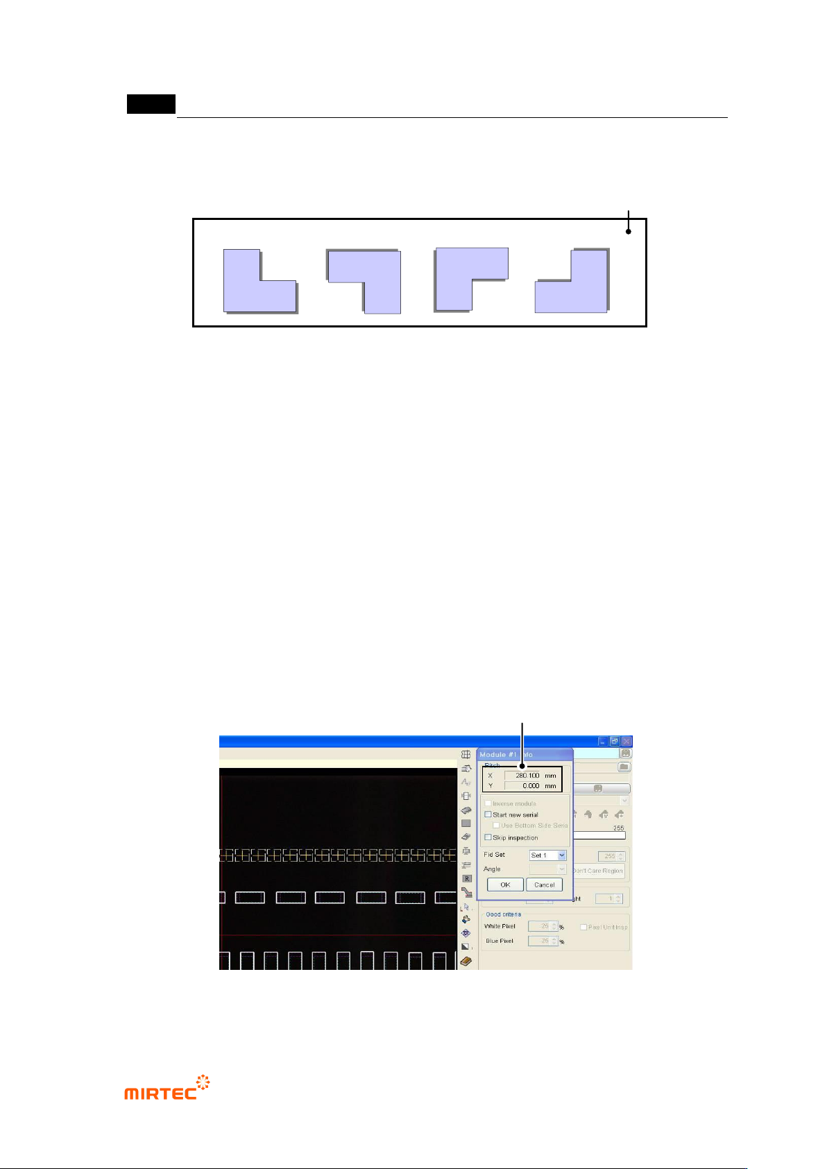
This function is used when component of base module is different from configuration or used for
teaching for 90° rotated module.
[Figure 5-289 Example of new module creation function]
Create compensation mark after moving module to a new area and teaching for conduct the
relevant component.
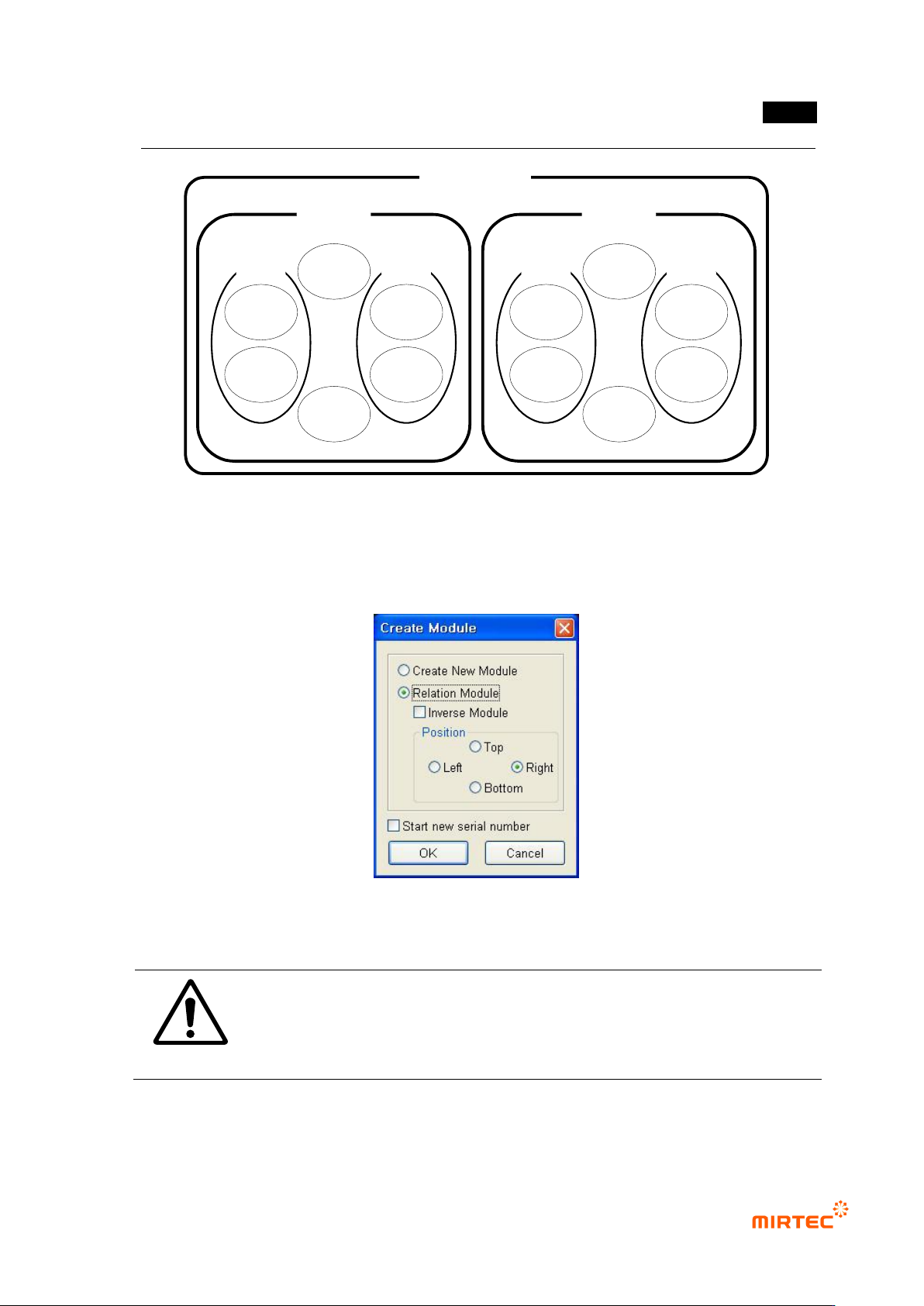
Creating connecting module
i. Use this when module to be added is same with component configuration of base
module, and select one of up/down/left/right direction for position based on base
module.
ii. In case of reverse module, check at „reverse module‟.
iii. Robot will automatically move to the first compensation mark position of reference
module, and compensation mark window will be displayed at the center of frame
image screen.
iv. To display window that completed teaching in frame image screen, select random
frame in whole image screen.
v. Move robot to the position where there is component of added module while
pressing the left button of mouse in frame image screen, and click <OK> button in
module screen to finish connecting module creation.
[Figure 5-290 Connecting module creation screen]
Offset Distance between Standard Module and Creation Module
Basic module
Reverse module
New module
PCB
New module
错误!使用“开始”选项卡将 제목 2 应用于要在此处显示的文字。错误!使用“开始”选项卡将 제목 2 应用
于要在此处显示的文字。 .
5-225
Starting new serial No
If PCB size is not big, use this function to simultaneously inspect 2 PCBs for minor axis of time
for PCB mounting and ejecting.
Creation method is same with that of connecting module mentioned above. However, serial No of
the second PCB model must be entered at a same time when serial No is provided.
[Figure 5-291 serial No for inspection]
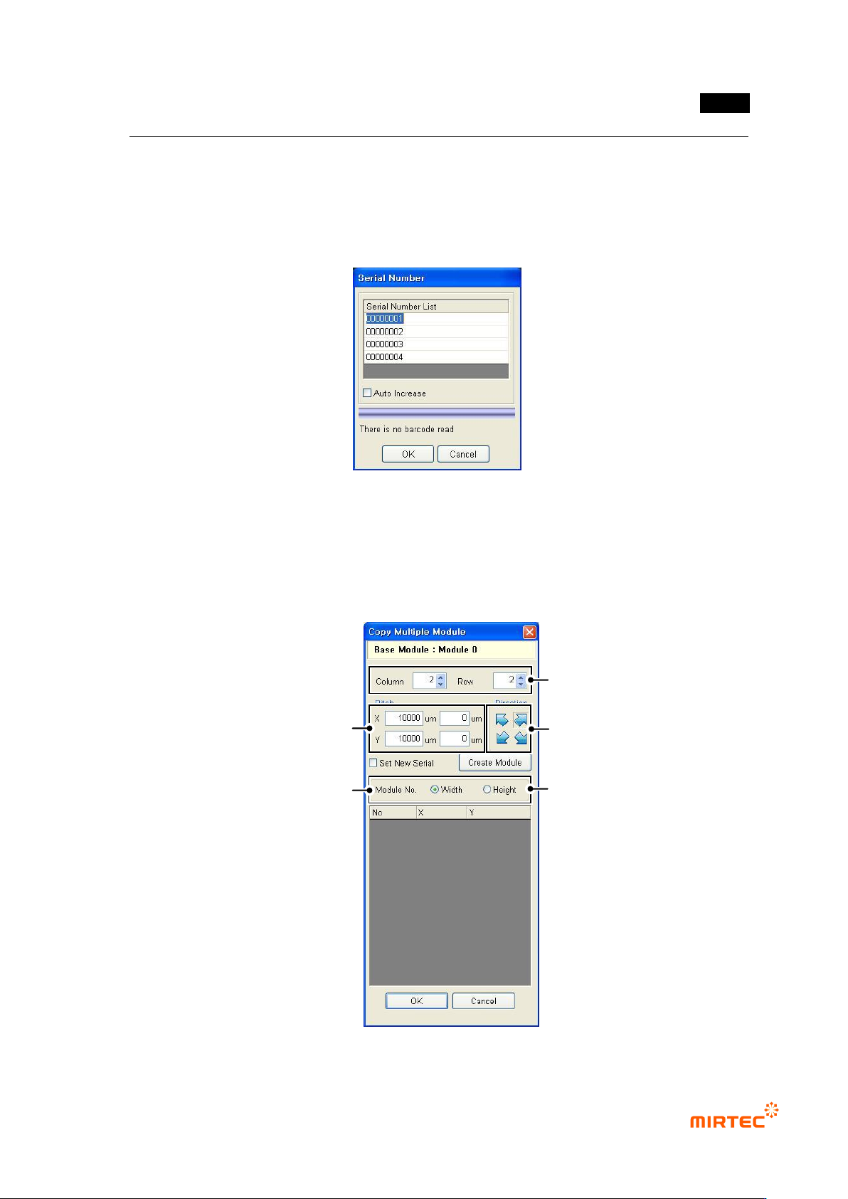
Adding multiple module
Multiple module copy is a function to create many modules at a time. If there are same
modules in 1 substrate, operator will judge number of width and height of module to be created
in multiple module copy screen, pitch between modules and module creation direction and
create desired number of module.
[Figure 5-292 multiple module copy]
Set low & line of module to create.
Decide direction to create module.
(Top Left, Top Right, Bottom Left,
Bottom Right)
Input pitch between the modules to create.
Pitch should be learned in advance.
After clicking <Create Module> button,
Create multi module.
Decide direction to create (Width/Length)