MV-9_Chapter 5. Teaching.pdf - 第229页
错误 ! 使用“开始” 选项卡将 제목 2 应用于要在此处显示的文字。 错误 ! 使用“开始”选项卡将 제목 2 应用 于要在此处显示的 文字。 . 5- 229 Compensatio n mark setting Check at „ board mark setti n g ‟ . Coordinate compensation (module compen satio n mark ) This function is …
MV-9 User Manual
5-228
Starting new serial No
Same with the description of new creation of PCB model of connecting module.
Skip mark setting
This option is used when inspection o specific module is not desired among connecting
modules. For this, display marking at certain position inside the module, and it is possible only
for base module.
Add, move, delete
Move robot to random position in a module, and click <Add> button in „inspection skip
mark‟ screen to draw window position in which marking will be displayed. For reduction of
inspection time, around compensation mark is recommended for marking position.
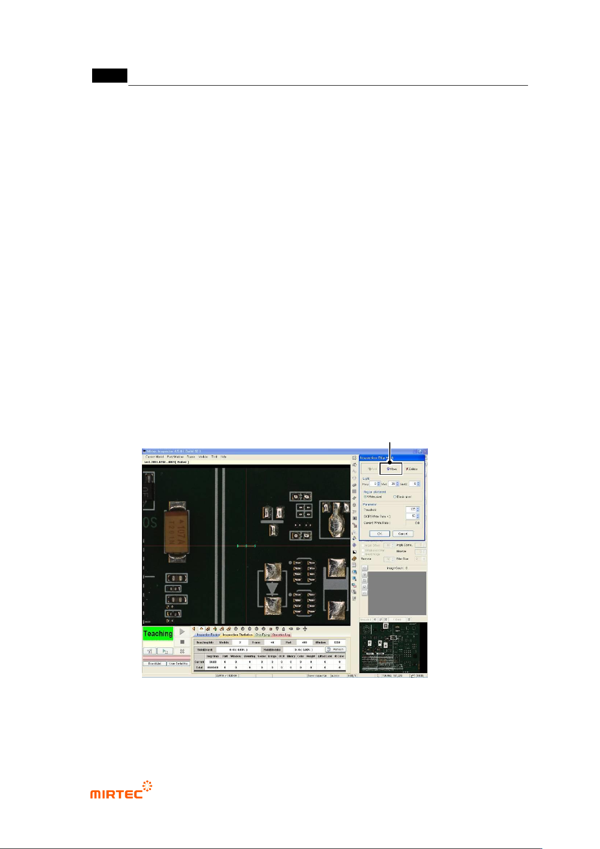
Light setting
Users can set light to get clearer image.
Interested area
Set inspection condition in area based on white pixel or black pixel
Parameter
If „current white ratio‟ value that changes whenever „binarization level‟ value is adjusted is
lower than „SKIP (white ratio<)‟ value, the relevant module will skip inspection.
[Figure 5-296 skip mark setting]
Move Robot to Marking Window Center
错误!使用“开始”选项卡将 제목 2 应用于要在此处显示的文字。错误!使用“开始”选项卡将 제목 2 应用
于要在此处显示的文字。 .
5-229
Compensation mark setting
Check at „board mark setting‟.
Coordinate compensation (module compensation mark)
This function is used to re-adjust position of compensation mark of each module.
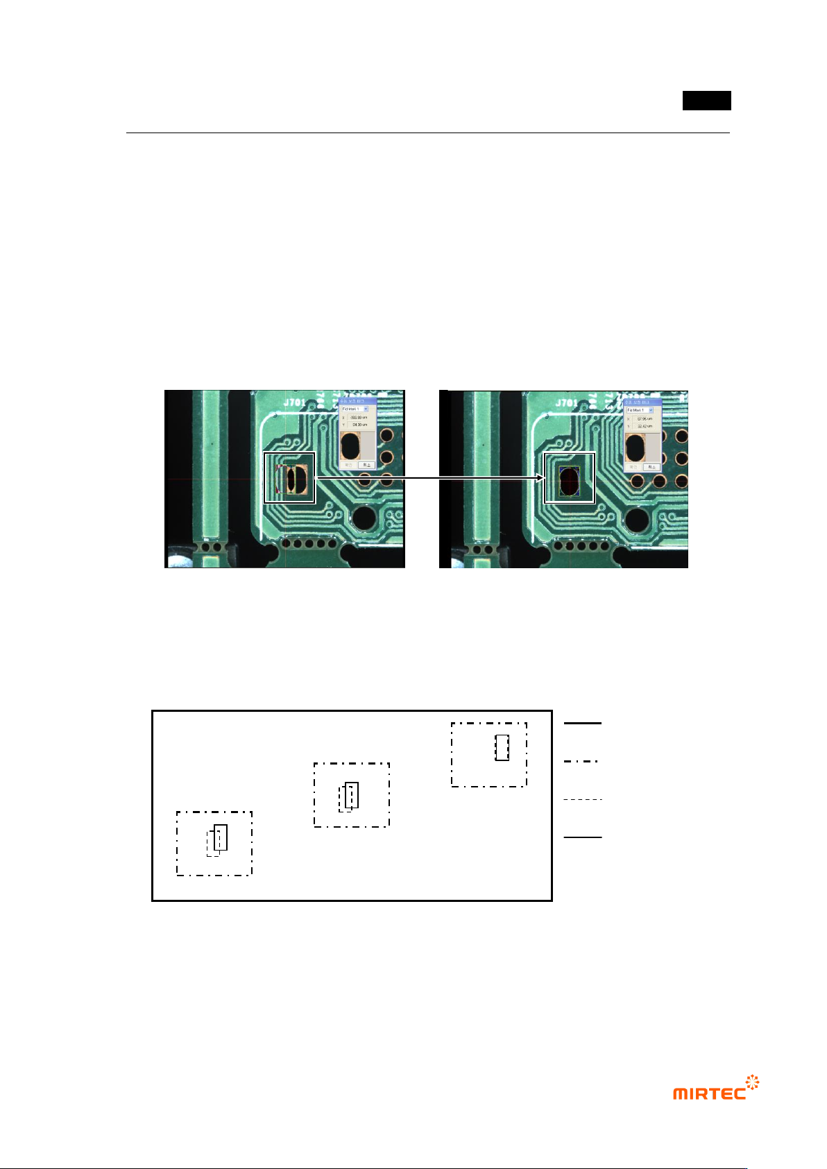
Setting of „manual compensation mark‟
Move to module desired to be modified, and execute „coordinate compensation (module
compensation mark)‟ menu to set „manual compensation mark‟.
Move compensation mark of „compensation mark 1‟ like the saved image to correct offset
position. correct offset position for „compensation mark 2‟ with method.
[Figure 5-297. compensation mark manual coordinate compensate]
Coordinate compensation (component)
If position move degree of inspection windows between frames of the relevant module is
different, use this to compensate window position move to diagonal direction. Generally, this is
used after machine copy for PCB model sharing between machines.
[Figure 5-298 Use example of module coordinate compensation]
Check whether inspection window correctly matches with component in the center of frame of
the relevant module. If there is, move to the relevant frame. If not, select „all frame‟ in popup
menu displayed by clicking right button of the mouse in whole image screen, and then match
inspection window in the frame to component using „frame move‟ function.
PCB
Frame
Inspection
window
Part
c
b
a
MV-9 User Manual
5-230
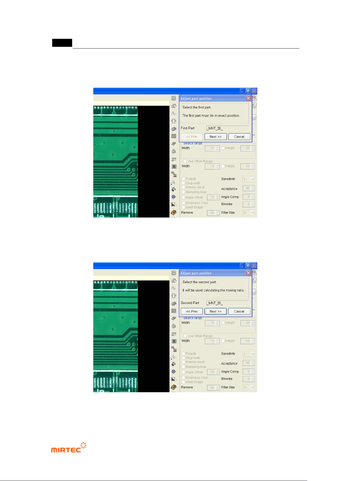
① Move robot to the frame in [Figure5-169]-(a) and select random 1 inspection window in
frame as show in the figure below. Click <Next> button in „component position
compensation‟ screen.
[Figure 5-299 Module coordinate compensation stage 1 - reference window selection]
② Move robot to the frame in [Figure5-169]-c, select random inspection window, and click
<Next> button in „component position compensation‟ screen.
[Figure 5-300 Module coordinate compensation stage 2 - selection of position twisted window]
③ Move the selected inspection window to component position, and click <Next> button in
„component position compensation‟ screen.