MV-9_Chapter 5. Teaching.pdf - 第230页
MV -9 Use r Manual 5- 230 ① M ove r obot to the fram e i n [Figure5- 169 ]-(a) and se l ect random 1 i nspection w i ndow in frame as show in the figure below . Cli ck <Next> button in „ component position com pens…
错误!使用“开始”选项卡将 제목 2 应用于要在此处显示的文字。错误!使用“开始”选项卡将 제목 2 应用
于要在此处显示的文字。 .
5-229
Compensation mark setting
Check at „board mark setting‟.
Coordinate compensation (module compensation mark)
This function is used to re-adjust position of compensation mark of each module.
Setting of „manual compensation mark‟
Move to module desired to be modified, and execute „coordinate compensation (module
compensation mark)‟ menu to set „manual compensation mark‟.
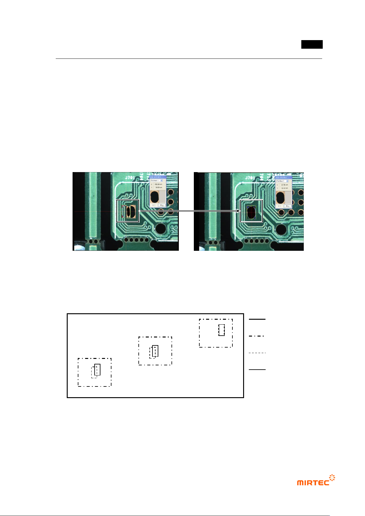
Move compensation mark of „compensation mark 1‟ like the saved image to correct offset
position. correct offset position for „compensation mark 2‟ with method.
[Figure 5-297. compensation mark manual coordinate compensate]
Coordinate compensation (component)
If position move degree of inspection windows between frames of the relevant module is
different, use this to compensate window position move to diagonal direction. Generally, this is
used after machine copy for PCB model sharing between machines.
[Figure 5-298 Use example of module coordinate compensation]
Check whether inspection window correctly matches with component in the center of frame of
the relevant module. If there is, move to the relevant frame. If not, select „all frame‟ in popup
menu displayed by clicking right button of the mouse in whole image screen, and then match
inspection window in the frame to component using „frame move‟ function.
PCB
Frame
Inspection
window
Part
c
b
a
MV-9 User Manual
5-230
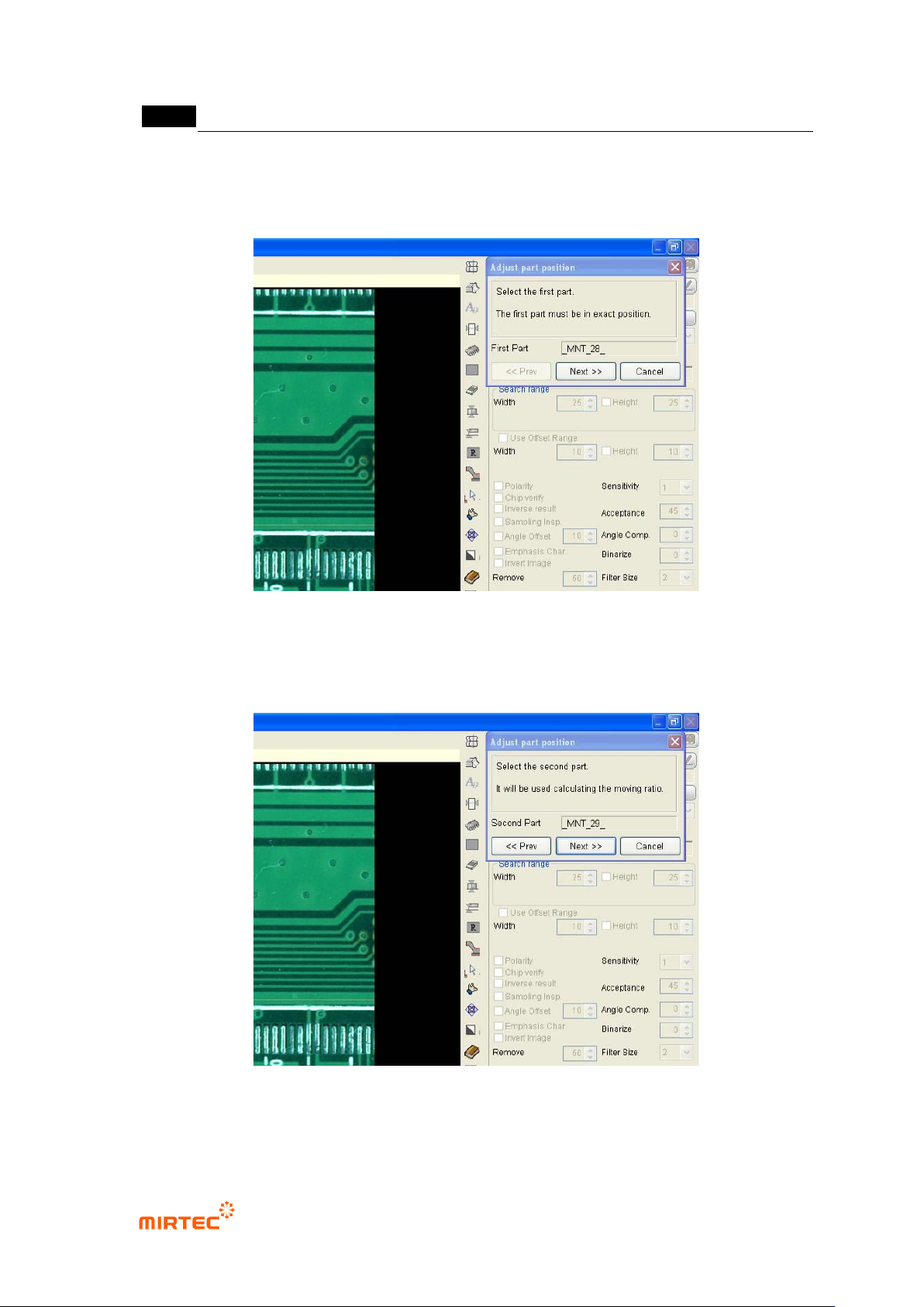
① Move robot to the frame in [Figure5-169]-(a) and select random 1 inspection window in
frame as show in the figure below. Click <Next> button in „component position
compensation‟ screen.
[Figure 5-299 Module coordinate compensation stage 1 - reference window selection]
② Move robot to the frame in [Figure5-169]-c, select random inspection window, and click
<Next> button in „component position compensation‟ screen.
[Figure 5-300 Module coordinate compensation stage 2 - selection of position twisted window]
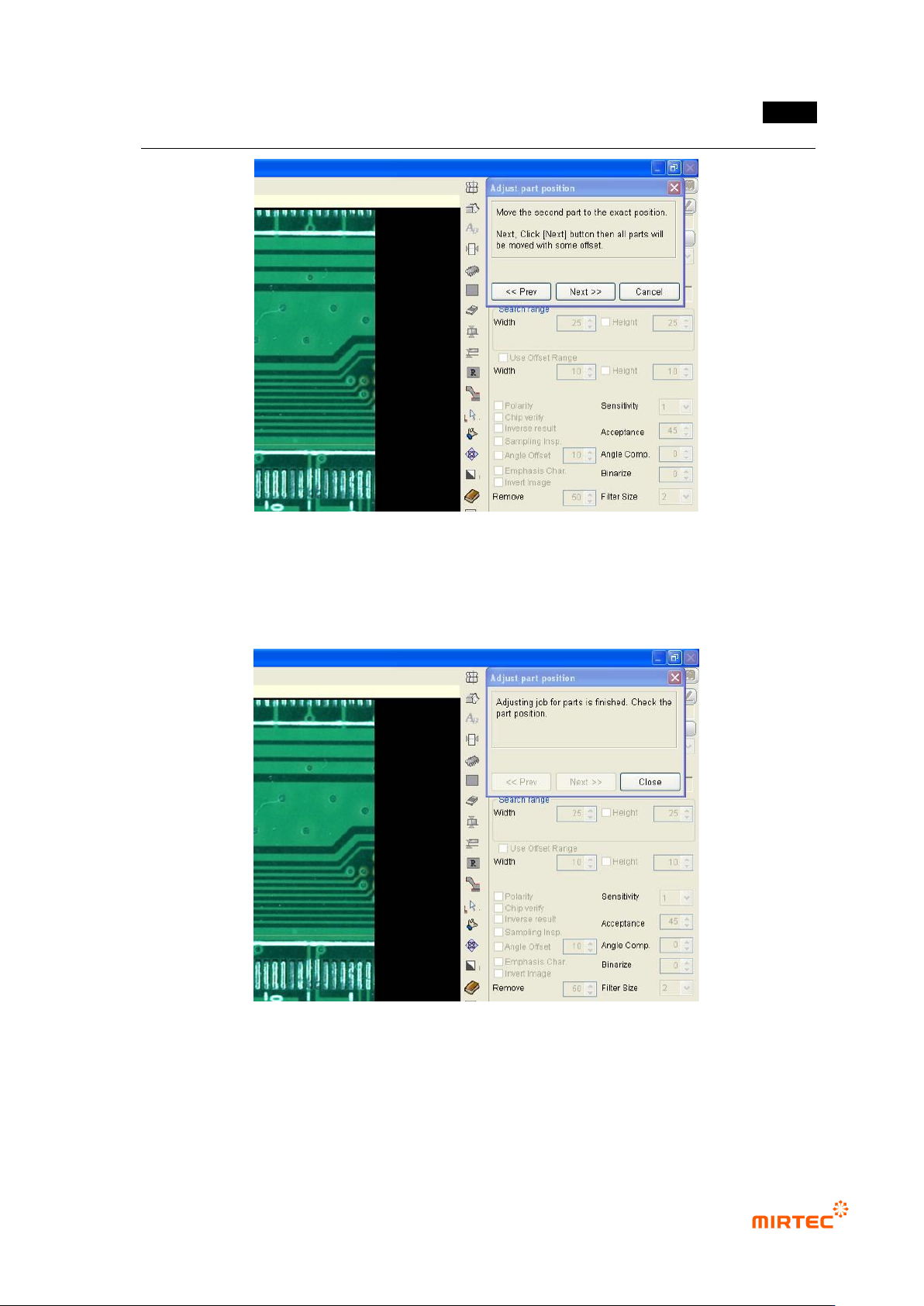
③ Move the selected inspection window to component position, and click <Next> button in
„component position compensation‟ screen.
错误!使用“开始”选项卡将 제목 2 应用于要在此处显示的文字。错误!使用“开始”选项卡将 제목 2 应用
于要在此处显示的文字。 .
5-231
[Figure 5-301 Module coordinate compensation stage 3 - move to position twisted window
component position]
④ Compensation value is internally calculated and the position of all inspection windows in
module will be compensated. Click <Close> button in „component position compensation‟
screen to finish module coordinate compensation.
[Figure 5-302 Completing module coordinate compensation]
Component position re-adjustment
Component position re-adjustment function is to re-adjust component position in each frame
using pattern matching method when component position in the currently selected module is
gradually twisted.