MV-9_Chapter 5. Teaching.pdf - 第233页
错误 ! 使用“开始” 选项卡将 제목 2 应用于要在此处显示的文字。 错误 ! 使用“开始”选项卡将 제목 2 应用 于要在此处显示的 文字。 . 5- 233 This is used to change format of serial No used during inspect i on and to re -set serial No. T o cha nge serial No form a t , cli ck <…
MV-9 User Manual
5-232
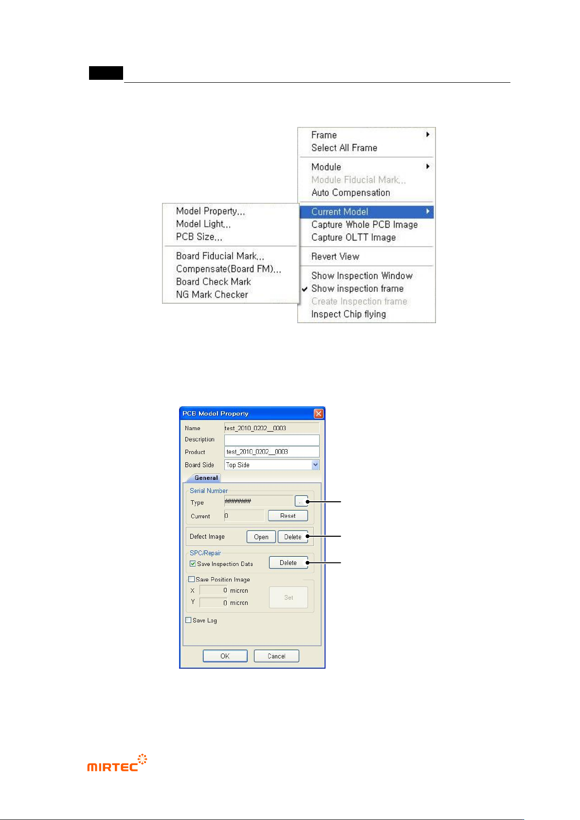
7) Current model related function
[Figure 5-303 current model menu]
This is used to edit information like light luminance value or NG marking use of currently opened
PCB model or change PCB size.
PCB model information ‘General’ tap
[Figure 5-304 PCB model information-general tap]
Serial No
Serial
Number
SPC & Repair
Improper Image
Folder
错误!使用“开始”选项卡将 제목 2 应用于要在此处显示的文字。错误!使用“开始”选项卡将 제목 2 应用
于要在此处显示的文字。 .
5-233
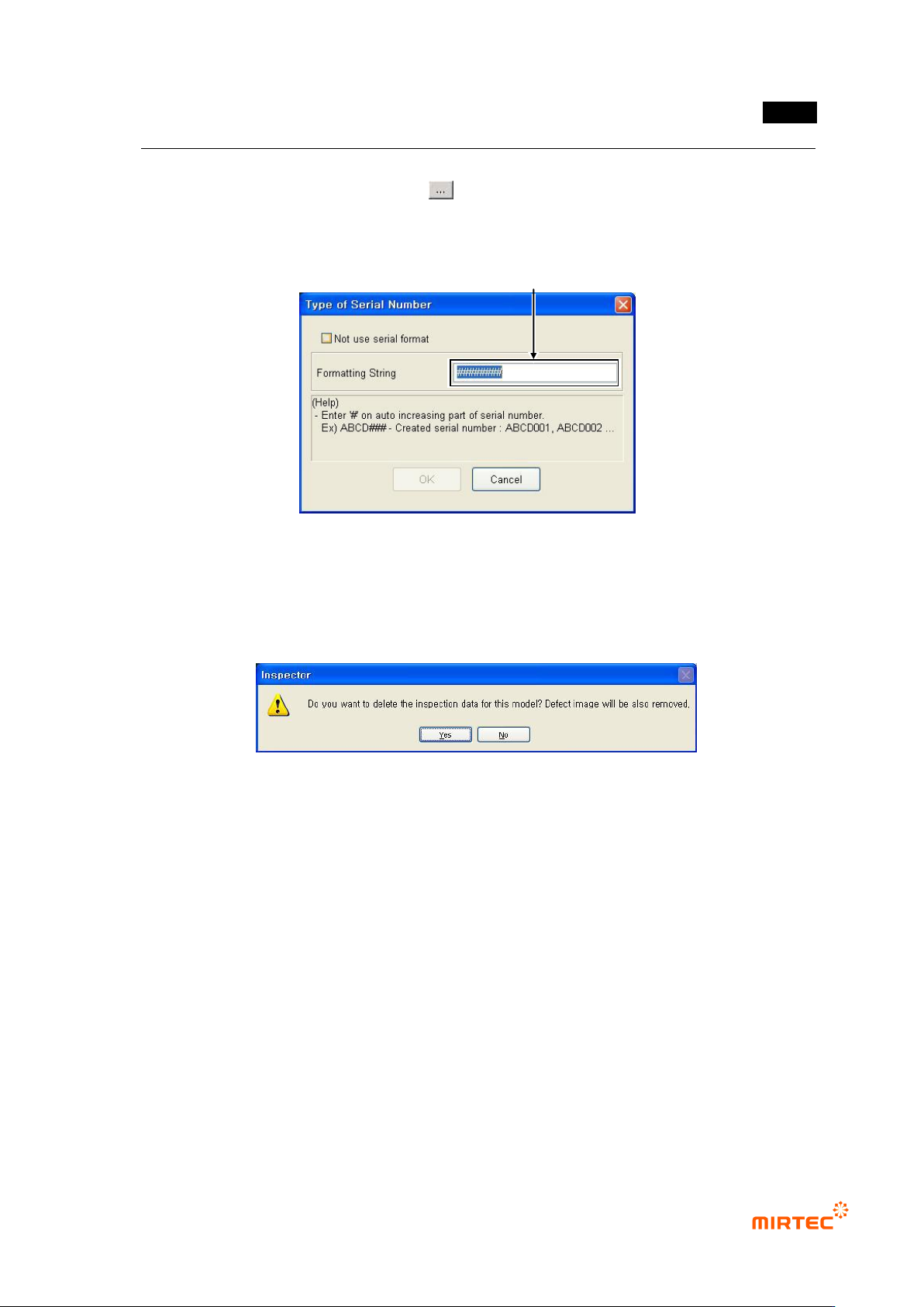
This is used to change format of serial No used during inspection and to re-set serial No.
To change serial No format, click < > button.
Change format character in serial No format as shown in the figure below and click <OK>
button.
[Figure 5-305 serial No format setting screen]
Default value
This is used to ignore serial No until now and reset serial No to „0‟. The screen below will
be displayed.
[Figure 5-306 DB data deletion selection]
Click <Yes (Y)> button to delete inspection DB data and defect image inspected so far
and reset serial No to „0‟. Click <No (N)> button not to delete inspection DB data but to
reset serial No to „0‟.
Defect image folder
Click <Open> button to open search screen as defect image save folder position of
current inspection model and to display or delete saved defect image. Click <delete>
button to delete all saved defect images.
SPC & repair
To display statistics data or defect information in SPC and repair program, SPC and repair
related option and „Save inspection result‟ option must be setting at „Config.‟ Click
<delete> button to remove DB data and defect image of all SPC and repair inspection
saved until now.
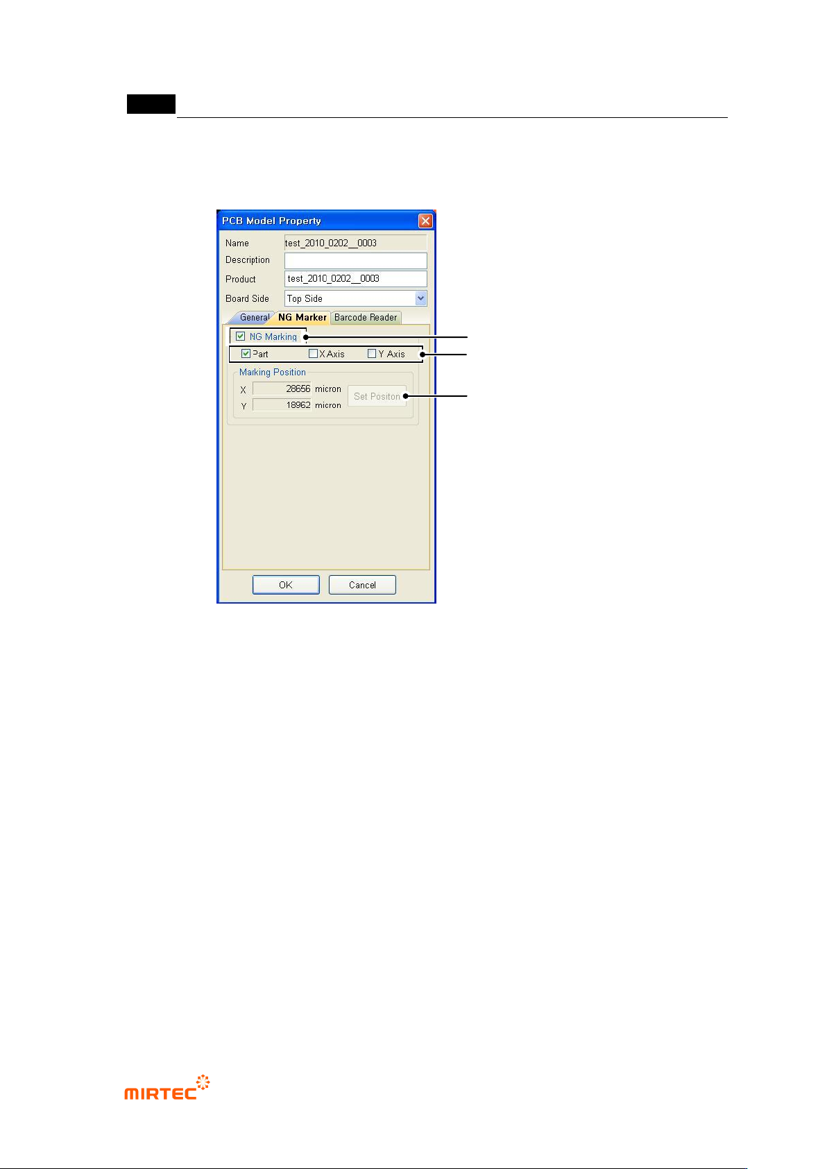
PCB model information ‘NG marker’ tap
Edit Type of Serial Number to Change.
MV-9 User Manual
5-234
This option will be activated only when „Use option device/NG marker‟ option in „machine
setting‟ in „login option‟ is checked. set parameter of NG marker related to NG marking for
defect component after model inspection.
[Figure 5-307 DB PCB model information - NG marker tap]
„NG marking‟ option
This option will be checked for NG marking for defect component after inspection.
Marking type setting
To designate marking at component center, select „component‟, and designate X/Y-axis
edge of board for defect component, select „X‟/„Y‟.
Marking position setting
i. Firstly, move robot to board edge to set X/Y position.
ii. Click <position setting> button that is activate when X/Y is selected.
iii. For marking of defect component at the center of the current position, move toward
X/Y-axis direction for marking.
Setting of NG Marking Use
Setting for Marking Type
Setting for Marking Location