MV-9_Chapter 5. Teaching.pdf - 第235页
错误 ! 使用“开始” 选项卡将 제목 2 应用于要在此处显示的文字。 错误 ! 使用“开始”选项卡将 제목 2 应用 于要在此处显示的 文字。 . 5- 235 [Figure 5- 308 X/Y-axi s marking po s ition setting] PCB model info rm atio n ‘ bar code reader ’ tap „ Op tion device/bar code reader ‟…
MV-9 User Manual
5-234
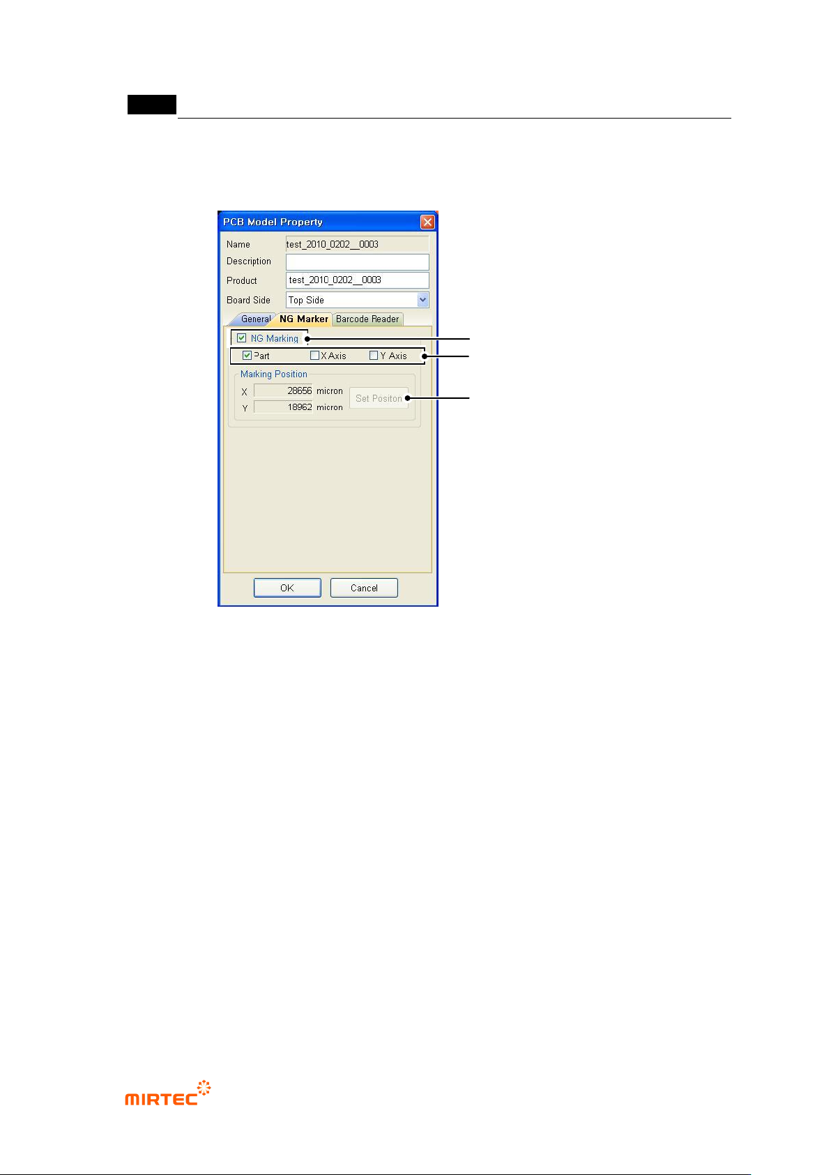
This option will be activated only when „Use option device/NG marker‟ option in „machine
setting‟ in „login option‟ is checked. set parameter of NG marker related to NG marking for
defect component after model inspection.
[Figure 5-307 DB PCB model information - NG marker tap]
„NG marking‟ option
This option will be checked for NG marking for defect component after inspection.
Marking type setting
To designate marking at component center, select „component‟, and designate X/Y-axis
edge of board for defect component, select „X‟/„Y‟.
Marking position setting
i. Firstly, move robot to board edge to set X/Y position.
ii. Click <position setting> button that is activate when X/Y is selected.
iii. For marking of defect component at the center of the current position, move toward
X/Y-axis direction for marking.
Setting of NG Marking Use
Setting for Marking Type
Setting for Marking Location
错误!使用“开始”选项卡将 제목 2 应用于要在此处显示的文字。错误!使用“开始”选项卡将 제목 2 应用
于要在此处显示的文字。 .
5-235
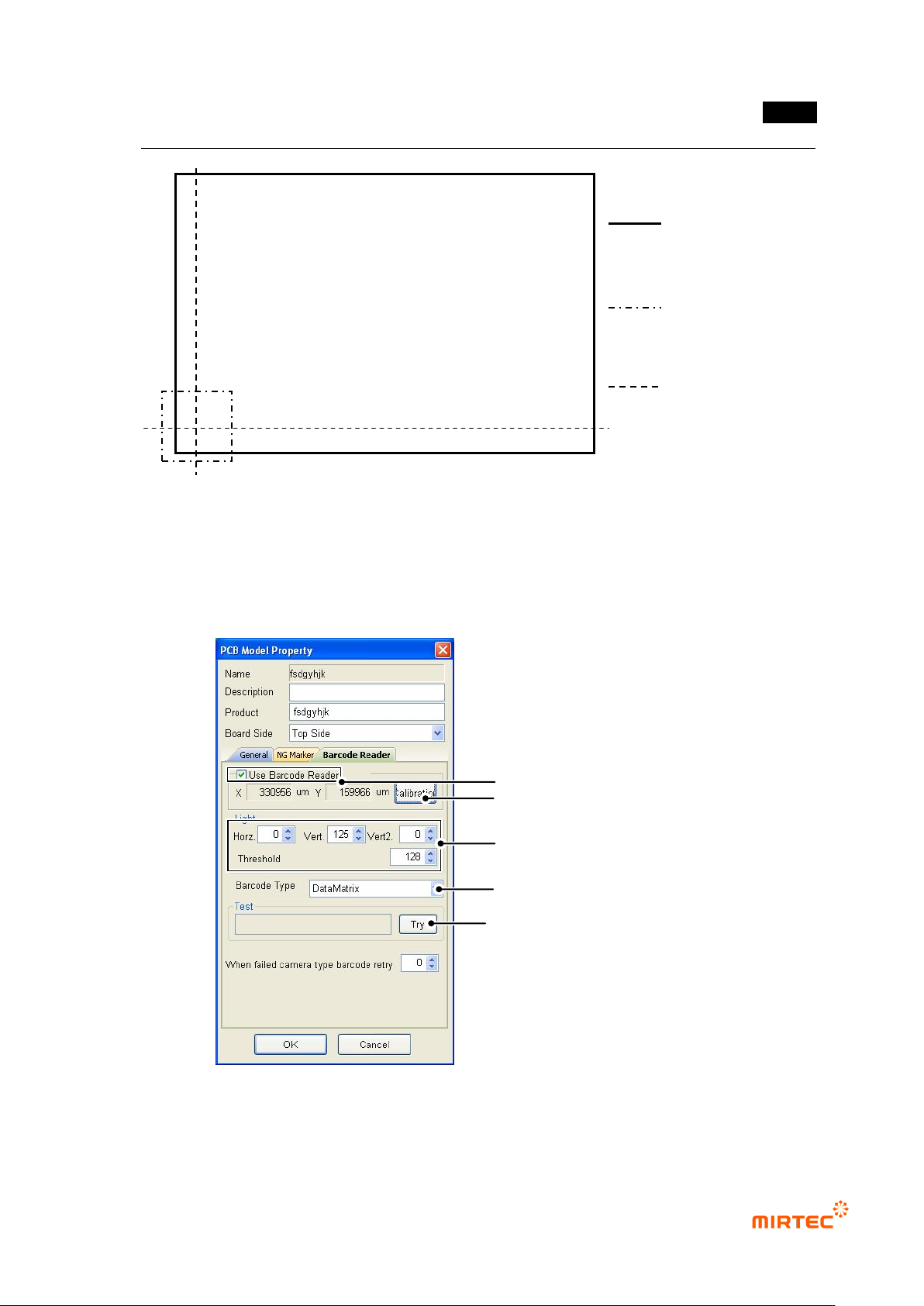
[Figure 5-308 X/Y-axis marking position setting]
PCB model information ‘bar code reader’ tap
„Option device/bar code reader‟ must be set in „machine setting‟ in „login option‟. When
inspection is started, serial No of inspection model can be read at bar code position by reading
bar code.
[Figure 5-309 PCB model information – bar code reader tap]
„Bar code reader‟ option
Whether to Use Bar Code
Setting for the coordinate of barcode
Light Setting
Setting for the type of the barcode
Barcode Connection Test
PCB
Frame position of current robot
X/Y axis line for marking

MV-9 User Manual
5-236
Check this option to read serial No of inspection model from barcode to start inspection.
Bar code coordinate setting
Set bar code position of inspection model.
Light setting
Set light in which bar code is clear and read binarization.
Bar code type setting
Set barcode type according to type of bar code that is used.
Bar code connection test
After completing all settings, click <Try> button to check connection status.
Model light
This is used to set luminance value of each light type for the relevant model. For more
information, refer to „light setting‟ in „Chapter 4 Config.‟.
Model area setting
This is used to re-set size of PCB model. setting method is same with PCB model size setting
method during new model creation.
8) Total image
This option is used to re-image total image of PCB. If this is selected, robot will move to machine
origin and start total image of PCB.
9) Creating OLTT image
If OLTT image is needed, select this to image OLTT image.
10) Cancelling enlarge/reduce (Applied for HD)
This function is to enlarge the current frame as large as 4 times. This will be used for precise
window teaching or checking.
11) Displaying inspection window
This function is to display inspection windows in whole image screen.
12) Flipped chip inspection