MV-9_Chapter 5. Teaching.pdf - 第249页
错误 ! 使用“开始” 选项卡将 제목 2 应用于要在此处显示的文字。 错误 ! 使用“开始”选项卡将 제목 2 应用 于要在此处显示的 文字。 . 5- 249 5.6 3D T eaching The objective is to inspect the lift of even p arts (Chip) . 5.6.1 Sel ection of W indow for M oun ting I nspection With …

MV-9 User Manual
5-248
This is to equally adjust width interval of the selected inspection windows.
Same height interval
This is to equally adjust height interval of the selected inspection windows.
错误!使用“开始”选项卡将 제목 2 应用于要在此处显示的文字。错误!使用“开始”选项卡将 제목 2 应用
于要在此处显示的文字。 .
5-249
5.6 3D Teaching
The objective is to inspect the lift of even parts (Chip).
5.6.1 Selection of Window for Mounting Inspection
With the window button, select and add the window for mounting inspection.( ).
* In general, a new window is not added and “Use 3D Inspect“ option is checked and used on
the window for mounting inspection which has already been taught.
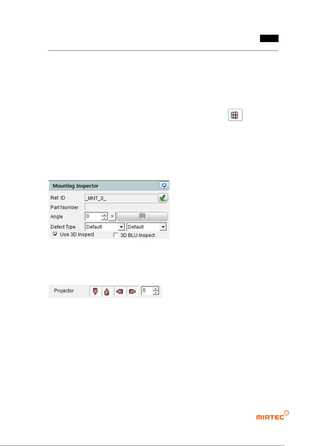
5.6.2 Selection of “Use 3D Inspect “Option
Check “Use 3D Inspect” item in the window parameters for mounting inspection.
5.6.3 Projector Selection
Select the projector to be used in the inspection.
- It is possible to select the east, west, south and north projectors, and they are selected
by default values.
- In general, it is recommended that 4 projectors be used.
In case only one projector is used, the measurement may not be made due to noise.
MV-9 User Manual
5-250
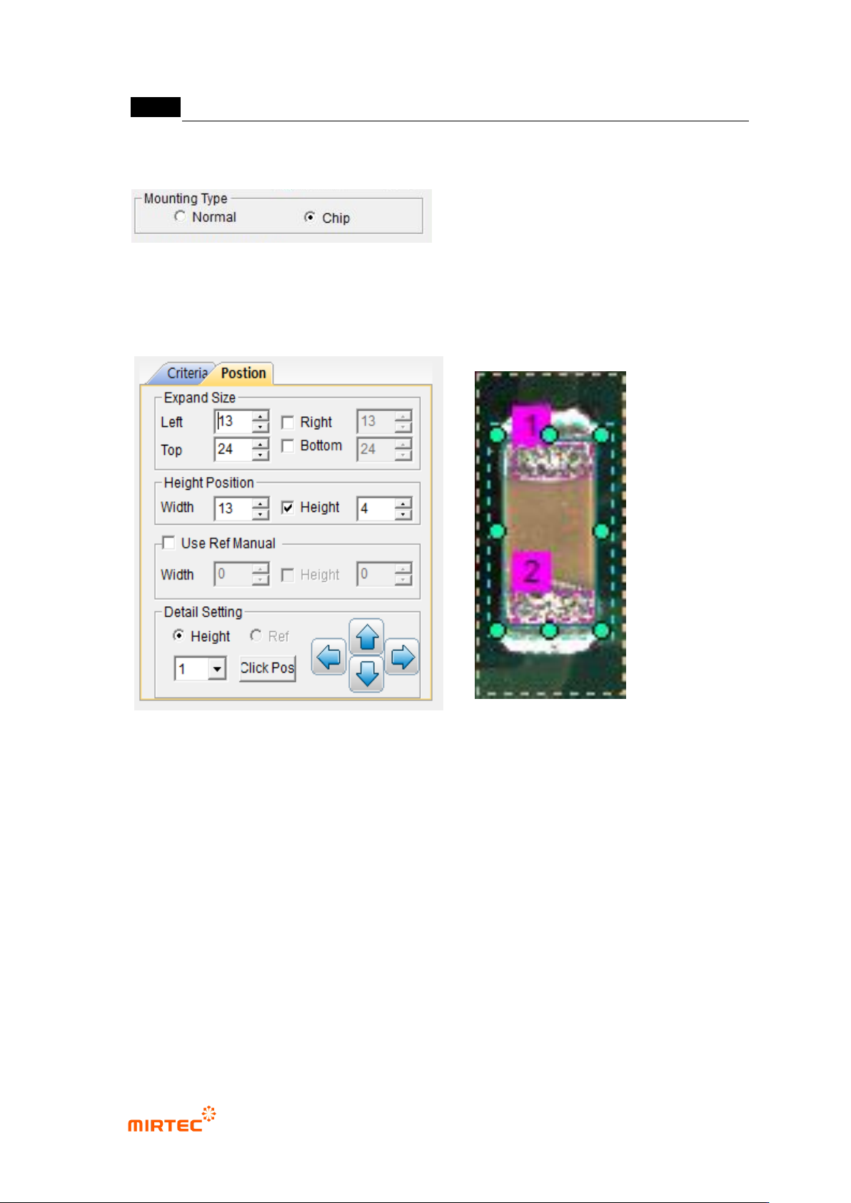
5.6.4 Selection of Mounting Type
- Select “Chip” in the mounting type.
5.6.5 Position Setting
④ Setting of Expanded Size
- Decide the expanded size for planar information with respect to the floor (PCB or
reference).
- Include the floor surface from all the directions of left, right, top and bottom.
- Mark the expanded area with yellow dotted lines.
Setting of Height Position
- Set the position to calculate the average height of the electrode part at both ends.
- Mark the height position with red dotted lines.