MV-9_Chapter 5. Teaching.pdf - 第254页
MV -9 Use r Manual 5- 254 5.7 Odd Part s The objective is to inspect the lift of odd p arts (BGA, Connecto r , etc.). 5.7.1 Selection of W indow for M ounting Inspec tion With the window button, select and add the w indo…
错误!使用“开始”选项卡将 제목 2 应用于要在此处显示的文字。错误!使用“开始”选项卡将 제목 2 应用
于要在此处显示的文字。 .
5-253
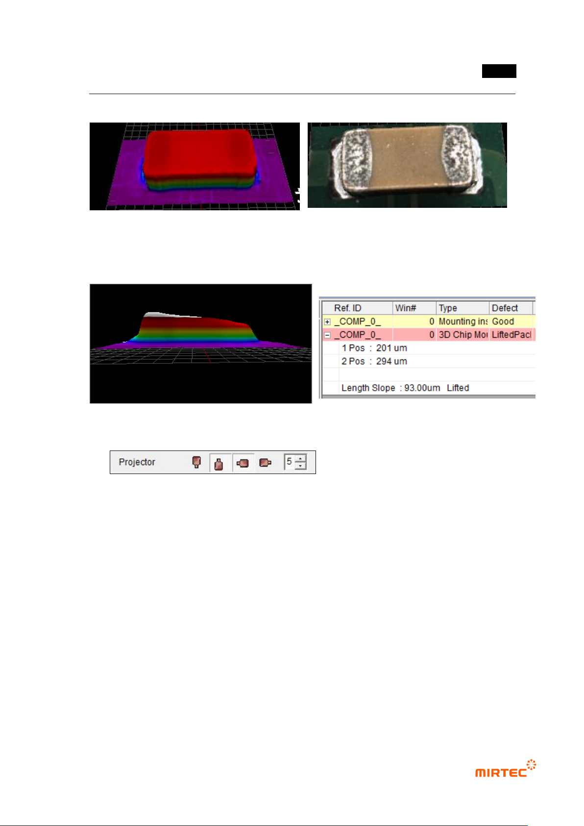
⑫ 3D Model is shown while the Full Image is converted to the tap of 3D Viewer.
<Color Map> <Texture Mapping>
⑬ Example for Poor Quality due to Lift
5.6.9 Reliability Threshold
The height data with low reliability are treated as invalid values in order to remove the
shadow.
- In case the data reliability is lower than the set threshold, the data are treated as
invalid values.
- In case of black-series parts, it may seem that the measurement is not made since
most of them are treated as invalid ones due to the low reliability.
- In case the 3D model of black-series parts does not show the normal form, try again
by lowering the threshold value.
- If the threshold value gets too low, the shadow may not be removed and noise may
be expressed.
MV-9 User Manual
5-254
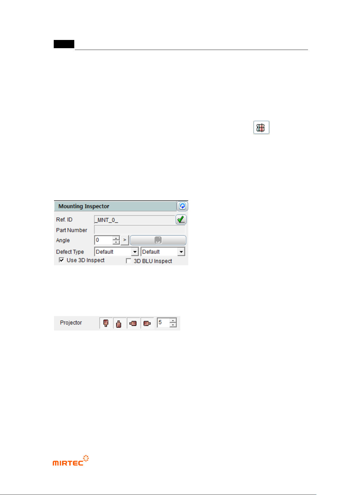
5.7 Odd Parts
The objective is to inspect the lift of odd parts (BGA, Connector, etc.).
5.7.1 Selection of Window for Mounting Inspection
With the window button, select and add the window for mounting inspection.( ).
* In general, a new window is not added and “Use 3D Inspect“ option is checked and used on
the window for mounting inspection which has already been taught.
5.7.2 Selection of “Use 3D Inspect “ Option
Check “Use 3D Inspect” item in the window parameters for mounting inspection.
5.7.3 Projector Selection
Select the projector to be used in the inspection.
- It is possible to select the east, west, south and north projectors, and they are selected
by default values.
- In general, it is recommended that 4 projectors be used.
In case only one projector is used, the measurement may not be made due to noise.
.
错误!使用“开始”选项卡将 제목 2 应用于要在此处显示的文字。错误!使用“开始”选项卡将 제목 2 应用
于要在此处显示的文字。 .
5-255
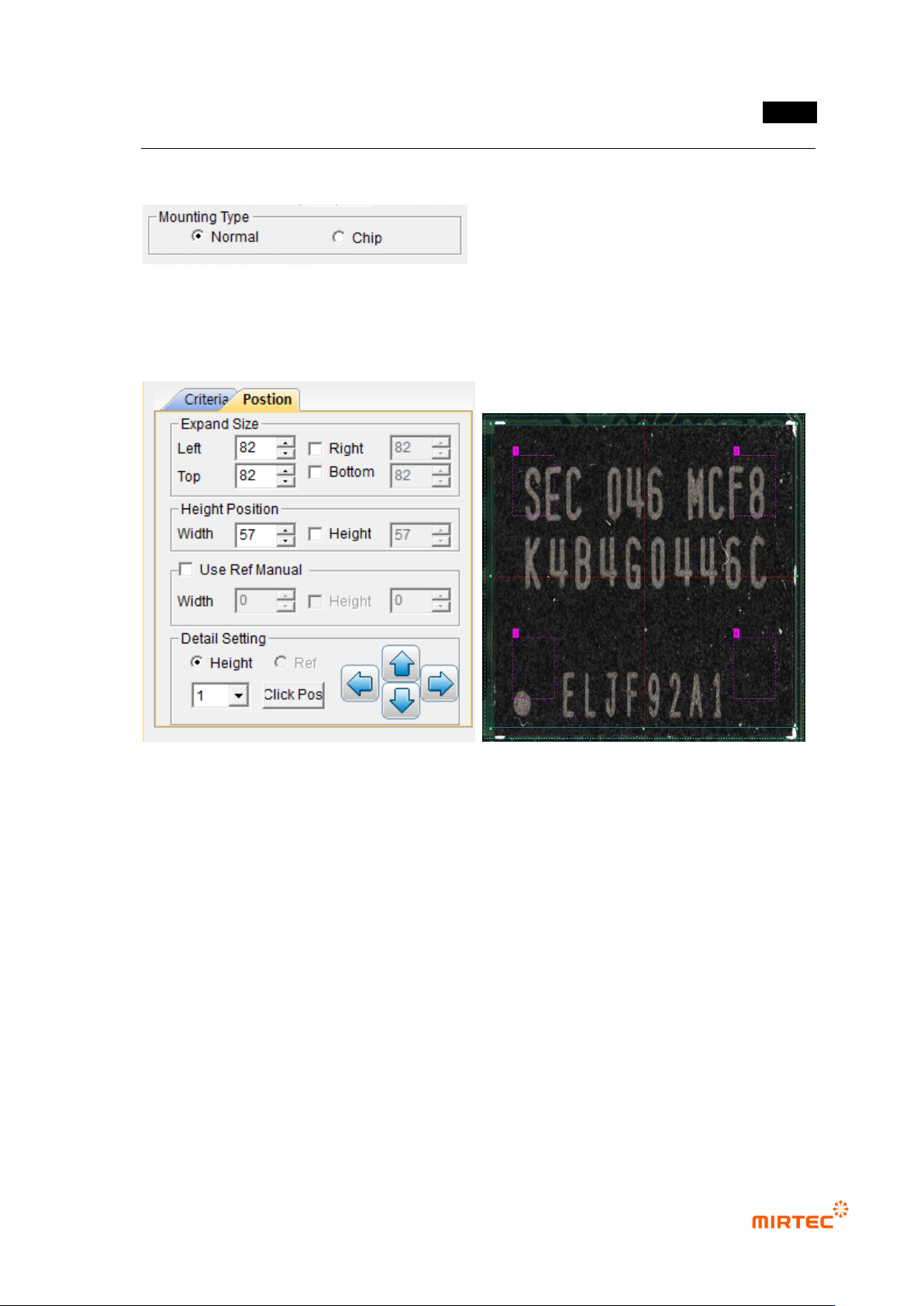
5.7.4 Selection of Mounting Type
Select “Normal” in the mounting type.
5.7.5 Position Setting
⑭ Setting of Expand Size
- Decide the expanded size for planar information with respect to the floor (PCB or
reference).
- Include the floor surface from all the directions of left, right, top and bottom.
- Mark the expanded area with yellow dotted lines.
Setting of Height Position
- Set the position to calculate the average height of the electrode part at both ends.
Mark the height position with red dotted lines.
⑮ Use Ref Manual (Setting of Reference Surface)
- Set manually the region for planar information.
- It is possible to set the height and size together or separately by using the check box.