MV-9_Chapter 5. Teaching.pdf - 第266页
MV -9 Use r Manual 5- 266 5.9.4 Selection of LED PKG . T ype <T op View T ype> <Side View T yp e> Select LED T ype. - T op View: This is t he type to relea se li ght to th e top where LED PKG . is mounted. - …
错误!使用“开始”选项卡将 제목 2 应用于要在此处显示的文字。错误!使用“开始”选项卡将 제목 2 应用
于要在此处显示的文字。 .
5-265
5.9 BLU
The objective is to inspect the Shift, Rotation, Lift, and Polarity of BLU.
5.9.1 Selection of Window for Mounting Inspection
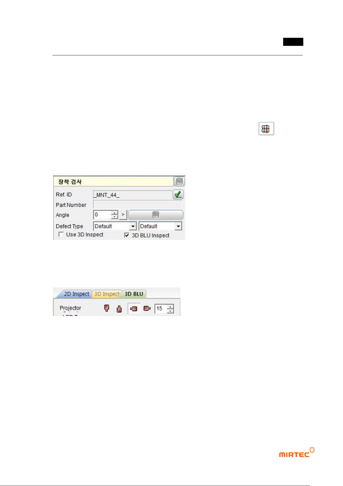
With the window button, select and add the window for mounting inspection..( ).
5.9.2 Selection of “3D BLU Inspect “ Option
Check “3D BLU Inspect” item in the parameters for the mounting inspection window.
5.9.3 Projector Selection
Select the projector used in the inspection.
- In general, two 3D projectors are installed in 7-SB, the BLU inspection equipment..
- It is a basic set value to use only one projector in BLU inspection..
- Reduce the shadow using the reliability.
MV-9 User Manual
5-266
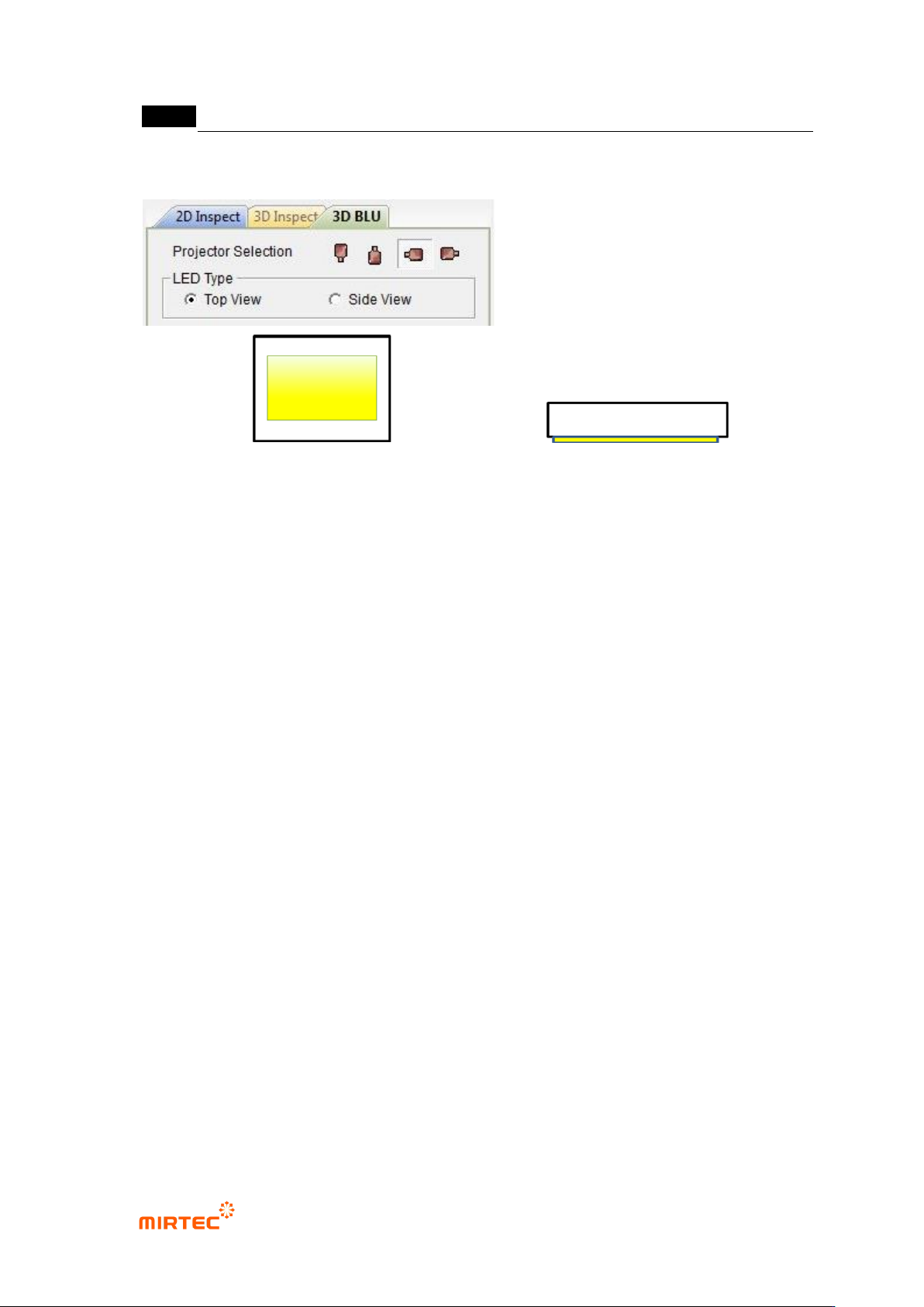
5.9.4 Selection of LED PKG. Type
<Top View Type> <Side View Type>
Select LED Type.
- Top View: This is the type to release light to the top where LED PKG. is mounted.
- Side View: This is the type to release light to the side where LED PKG. is mounted.
错误!使用“开始”选项卡将 제목 2 应用于要在此处显示的文字。错误!使用“开始”选项卡将 제목 2 应用
于要在此处显示的文字。 .
5-267
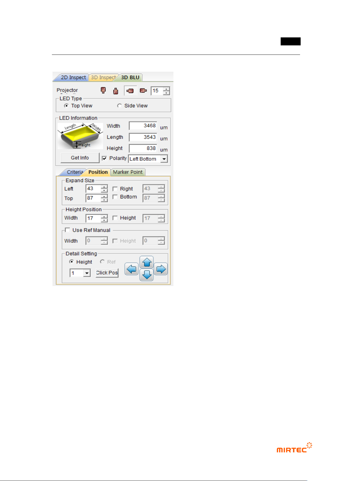
5.9.5 Position Setting
31 Setting of Expanded Size
- Determine the expanded size to obtain planar information with respect to the floor (PCB
or reference).
- Include the floor surface from all the directions of left, right, top, and bottom.
- Mark the expanded region with yellow dotted lines.
32 Setting of Height Position (Region)
- Set the region to calculate the average height of the electrode parts at both ends.
- Mark the height region with red dotted lines.
33 Use Ref Manual (Setting of Reference Surface)
- Set the region to obtain the planar information for the reference surface.