MV-9_Chapter 5. Teaching.pdf - 第27页
错误 ! 使用“开始” 选项卡将 제목 2 应用于要在此处显示的文字。 错误 ! 使用“开始”选项卡将 제목 2 应用 于要在此处显示的 文字。 . 5- 27 Red i m a ge Green image Blue image Lum i nance i m age [Figure 5- 20 Screen to cr eate mounting inspection window] 2) Example of teaching …
MV-9 User Manual
5-26
5.3.2. Mounting inspection window
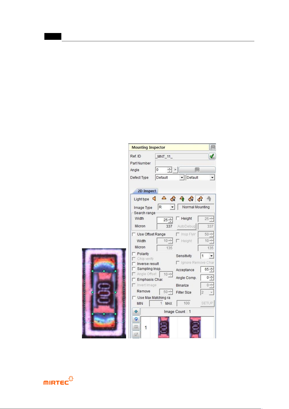
Mounting inspection window is used to inspect items like position secession or non-mounting,
wrong mounting for interesting component.
1) Teaching method
① Click <mounting inspection window> button among operating buttons.
② Draw inspection window in interesting component, and select light type and image type that
clearly divide component from PCB.
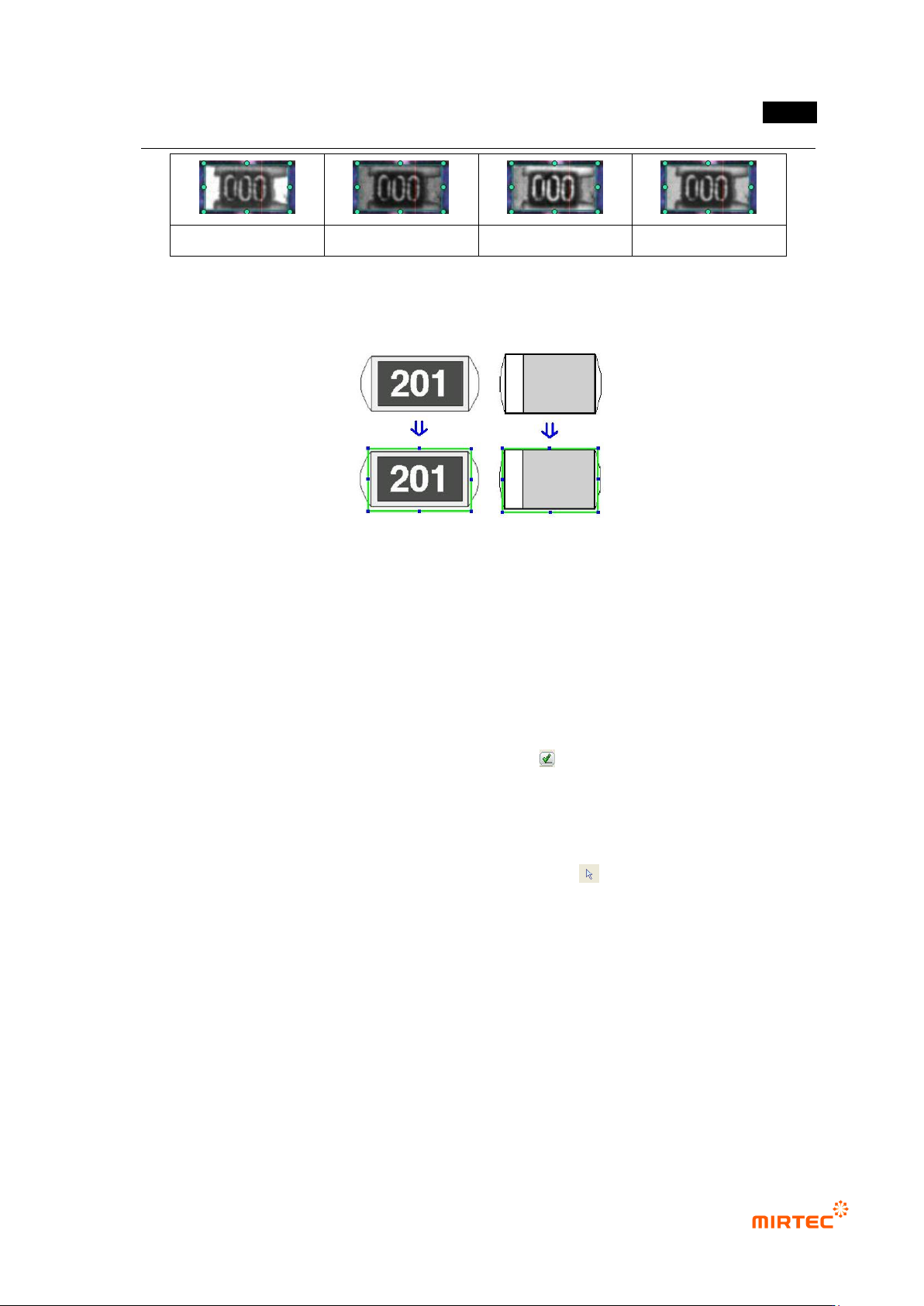
③ Select one of R (Red), G (Green), B (Blue) or L (Luminance) for image type. [Figure 5-37]
shows gray image according to image types.
[Figure 5-19 Screen to create mounting inspection window]
错误!使用“开始”选项卡将 제목 2 应用于要在此处显示的文字。错误!使用“开始”选项卡将 제목 2 应用
于要在此处显示的文字。 .
5-27
Red image
Green image
Blue image
Luminance image
[Figure 5-20 Screen to create mounting inspection window]
2) Example of teaching of a representative component
[Figure 5-21 Example of mounting inspection window teaching]
3) Parameter of mounting inspection window
Reference name
- Since reference name is automatically created while inspection window is being created, it
has unique name among PCB models.
- Created in „_MNT_1_‟ format. „MNT‟ means Mounting and the number means the order of
creating of mounting inspection window.
- To manually change reference name, click <check ( )> button and enter reference name.
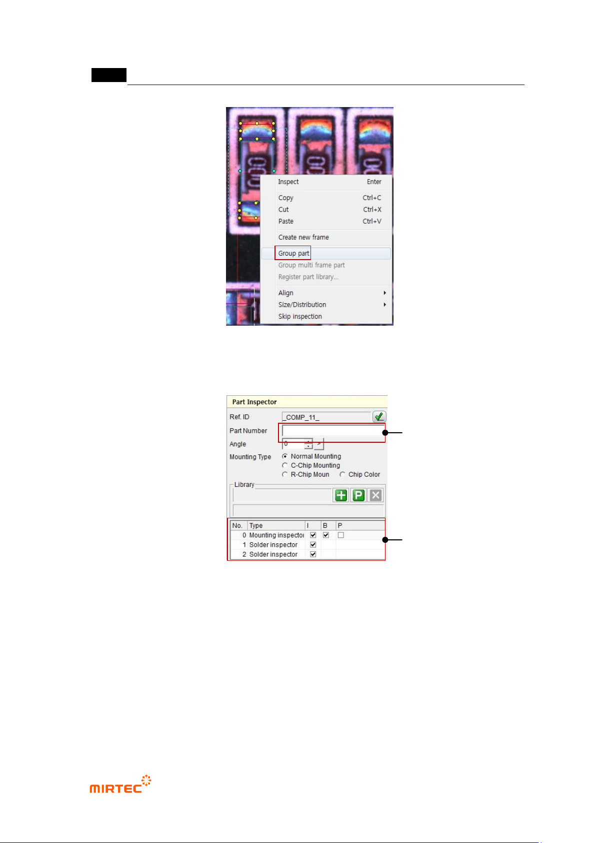
Component name
- To create many inspection windows for one component, group each inspection windows
into one component group and enter component name.
- To enter component name, firstly, click <object selection ( )> button among the operating
buttons and select inspection windows to be grouped. After that, select „Group component‟
popup menu displayed by clicking right button of the mouse.
MV-9 User Manual
5-28
[Figure 5-22 Creating inspection window component]
- When operation status screen is converted to component inspection window as shown in
[Figure 5-40], component name of the relevant component can be entered.
[Figure 5-23 Component inspection window screen]
Rotation angle
- Angle of inspection window will be displayed in 0 ~ 359° unit. Angle of window that is
created through manual teaching will be always displayed by 0°, and inspection window
will rotate counterclockwise based on the current position.
- If inspection window is created by using ATT, angle information of the relevant component
will be displayed.
- To re-image image at rotated position, click <refresh> button in pattern image screen.
part name
Grouped inspection
window list