MV-9_Chapter 5. Teaching.pdf - 第283页
错误 ! 使用“开始” 选项卡将 제목 2 应用于要在此处显示的文字。 错误 ! 使用“开始”选项卡将 제목 2 应用 于要在此处显示的 文字。 . 5- 283 5.10.3 Selec tion of Ref erence Positi on Select t he reference position window and select “Reference Position” on the param eter window .…
MV-9 User Manual
5-282
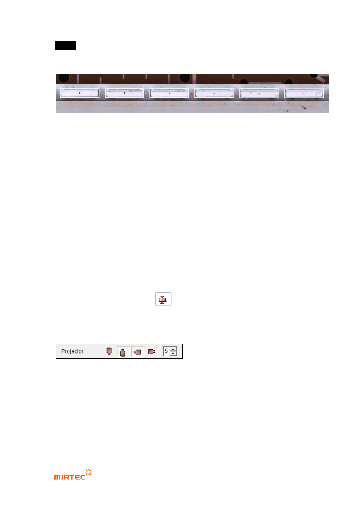
71 Setting of Reference Center Point for LED PKG during Automatic Teaching.
- The Reference Center Point of LED PKG is set during the automatic teaching.
- In case of not using the Marker, use the reference center point generated during the
automatic teaching.
- The reference center point generated during the automatic teaching is marked by a red
circle. (Do not mark in case of using the Marker.).
- In case of not using the Marker, no compensation is made for Bar Bending, which may
cause pseudo poor quality.
5.10 Height Checker
The objective is to inspect the height difference from the reference position.
5.10.1 Selection of Window for Height Inspection
With window button, select the height inspection window and add the window to the inspection
position and the reference position.( ).
5.10.2 Projector Selection
Select the projector to be used in the inspection.
- It is possible to select the east, west, south or north projector. Select the east and
south projector by default.
错误!使用“开始”选项卡将 제목 2 应用于要在此处显示的文字。错误!使用“开始”选项卡将 제목 2 应用
于要在此处显示的文字。 .
5-283
5.10.3 Selection of Reference Position
Select the reference position window and select “Reference Position” on the parameter
window..
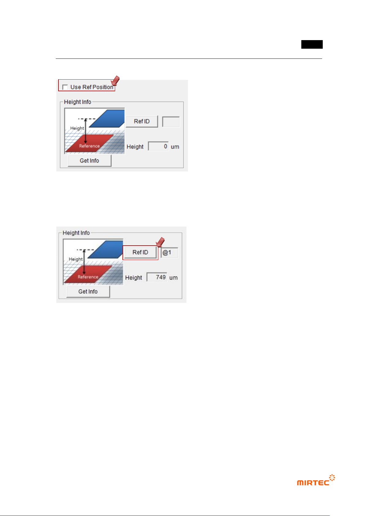
5.10.4 Designation of Reference Position
① Select the height inspection window and the reference position window, and tie them
into one part.
② Select the tied part and enter „Edit‟ mode.
③ Select the height inspection window and click “Reference ID” on the parameter
window.
④ Click the reference position window and designate the reference position. .
⑤ The ID of the window designated next to “Reference ID” is displayed.
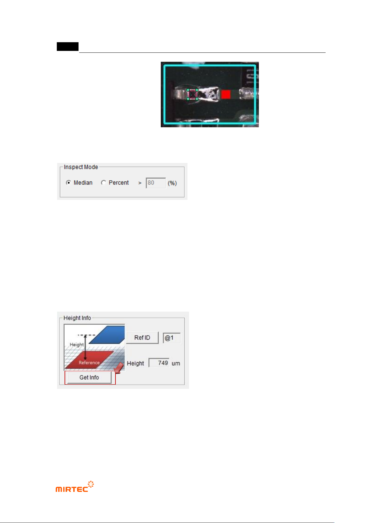
Example) The window selected in the figure below is the height inspection window and the
MV-9 User Manual
5-284
reference position is the red window.
5.10.5 Inspection Mode Setting
Set the inspection mode.
① Middle Value: Inspect it by using the middle value of the measured heights and the
inspection standards.
② Percentage: Inspect it by using the ratio of the heights satisfying the inspection
standards.
- Conduct the ratio-based inspection with the data satisfying the minimum and maximum
heights.
5.10.6 Criteria Setting
① Click “Measure”
- Measure and display the height.
② Inspection Standard Setting
- Set the reference value of the minimum and maximum heights in reference to the
measured heights.