MV-9_Chapter 5. Teaching.pdf - 第30页
MV -9 Use r Manual 5- 30 Light type - This is to set light for inspection of th e rel evan t inspection window that com pl eted teaching. The scr e en b e l ow w ill be displayed when li ght type i s changed. C li ck &…
错误!使用“开始”选项卡将 제목 2 应用于要在此处显示的文字。错误!使用“开始”选项卡将 제목 2 应用
于要在此处显示的文字。 .
5-29
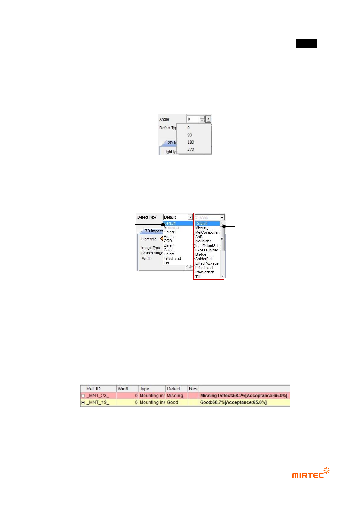
- In case of IC/Bridge teaching, basically rotate Bridge rightward for component teaching.
After adjusting rotation angle, make sure to click reset button to set initial value.
- In case of „Group component‟, angle must be same.
- If rotated component is saved in the library, angle value will be also saved to automatically
apply rotation value to component.
[Figure 5-24 Rotation angle input and selection]
Defect type
- As shown in [Figure 5-42], list to set inspection algorithm and defect type will be displayed
in each window screen to set detailed defect type.
[Figure 5-25 Detailed defect type list]
- The first selection item is inspection algorithm and the second selection item is detailed
defect type.
- If both of 2 selected items are selected as „default value‟, defect type set as inside defect
type and displayed. In other words, defect type judged by algorithm will be displayed.
- If defect type that excludes „default value‟ is selected, detailed setting defect type will be
displayed when defect occurs in the relevant window. In other words, if inspection
algorithm I set to „mount‟ and detailed defect type is set to „non-mounting‟, non-mounting
defect will be displayed when defect occurs in the relevant window.
[Figure 5-26 Detailed defect type result display status]
Select inspect algorithm
Detailed defect type
MV-9 User Manual
5-30
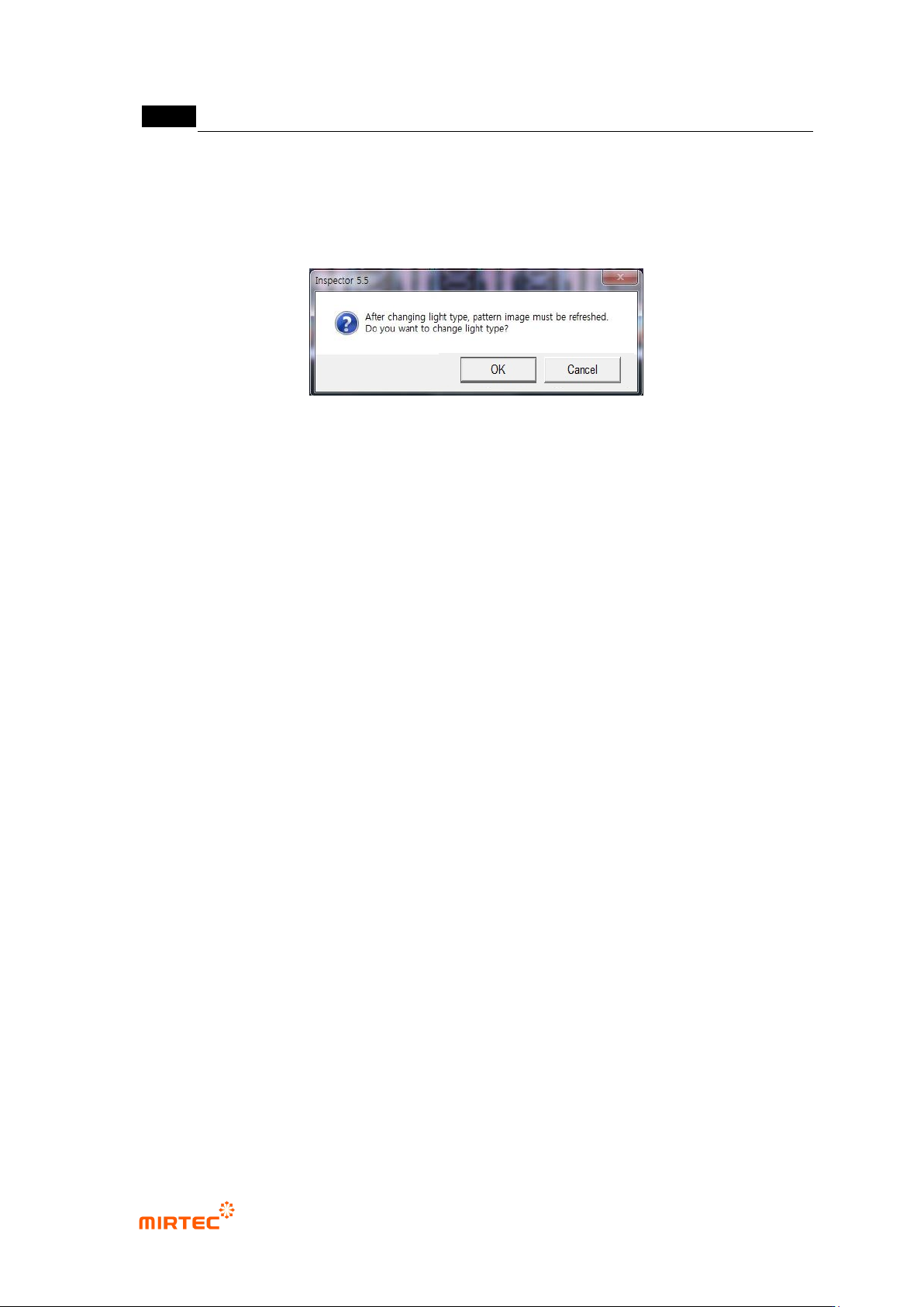
Light type
- This is to set light for inspection of the relevant inspection window that completed teaching.
The screen below will be displayed when light type is changed. Click <Yes (Y)> button to
re-image and save image that is saved in the pattern image screen.
[Figure 5-27 Light type change screen]
Inspection type
- Inspection types means the type of component desired to be inspected. For teaching with
mounting inspection window, „Normal Mounting‟ will be displayed.
Search range
- Window that completed teaching can be set by pixel unit of width and height of area to be
searched in registered pattern image. Basically, width and area will be enlarge/reduced
with same value, and check at „check‟ button on the right of the area to set width and area.
Use offset region
- In case of window inspection that does not have 50% of offset region even though it is in
search range, judge as defect. It can be set by pixel unit of width and height of area.
Polarity
- Select this option to inspect component with polarity
Chip re-inspection
- This function is to re-inspect whether there is chip or not when image change is small
during chip inspection and false defect is decided. This function will be activated only when
inspection type is C chip or R chip.
Judge as good of defect
- This function is to reverse defect judgment result.
Sample inspection
- Sampling inspection will be conducted based on setting interval to reduce false defect ratio.
For more information, refer to „default setting (page 4-18)‟ in „Chapter 4 Config.‟.
Angle offset
- The range set as angle offset of shifted component will be judged as normal.
错误!使用“开始”选项卡将 제목 2 应用于要在此处显示的文字。错误!使用“开始”选项卡将 제목 2 应用
于要在此处显示的文字。 .
5-31
Angle compensation
- In case of defect because of shifted component, rotate frame image to left (-)/right (+) with
staff angle 3° of given angle for inspection. This function is used to reduce false defect that
occurs by shift.
<Ex: inspection angle = (±) Nⅹ step angle + mod (compensation angle, 3), 0 ≤ N <
(compensation angle/3) +1)
Hence, when angle compensation is 10°, rotation angle to be inspected will be ±1°, ±4°,
±7°, and ±10°. If inspection matching ratio is higher than reference matching ratio that is
set in specific rotation angle, inspection will be stopped.>
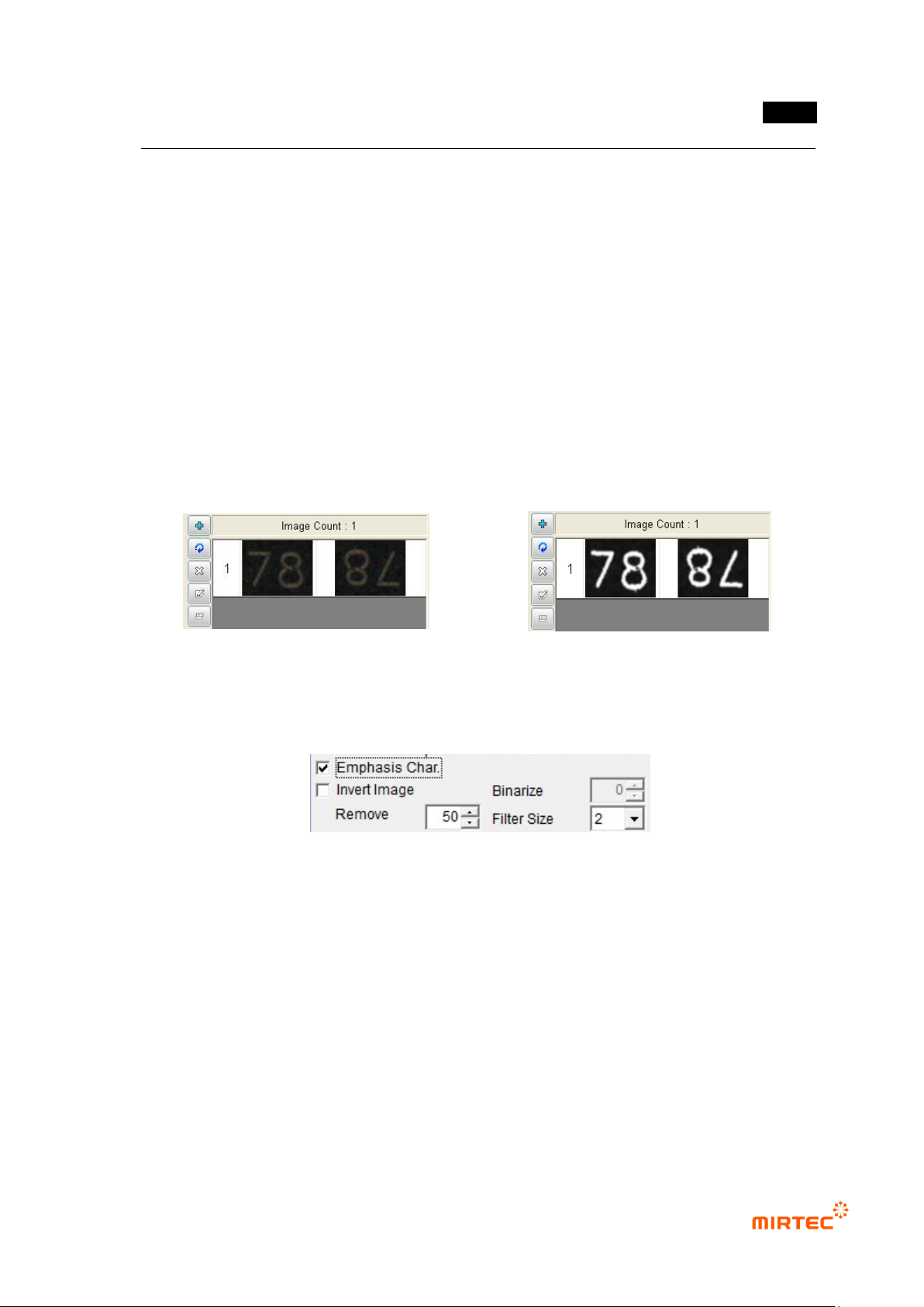
Character emphasis
- If character part of a component is not clear as shown in [Figure5-45], this function is to
clear character part by extracting only character part of a component through auto
binarization as shown in [Figure5-46].
[Figure 5-28 Pattern image before character
emphasis]
[Figure 5-29 Pattern image after character
emphasis]
Character emphasis parameter
[Figure 5-30 Character emphasis parameter]
Character emphasis
Set this option to use character emphasis.
Image reverse
In case of engraved character, this option is to reverse character emphasis image.
Noise removal
If character emphasis is selected, set size of max pixel that will be recognized as noise to
remove noise.
Filter size
If character emphasis is selected, filter size will adjust definition between background
image and character image.