MV-9_Chapter 5. Teaching.pdf - 第32页
MV -9 Use r Manual 5- 32 Binarization Manually set binarization value for more correct recogniti on after auto binar i zat i on of character i m a ge. Select pattern model desire d to b e manually set to se t binarizat…
错误!使用“开始”选项卡将 제목 2 应用于要在此处显示的文字。错误!使用“开始”选项卡将 제목 2 应用
于要在此处显示的文字。 .
5-31
Angle compensation
- In case of defect because of shifted component, rotate frame image to left (-)/right (+) with
staff angle 3° of given angle for inspection. This function is used to reduce false defect that
occurs by shift.
<Ex: inspection angle = (±) Nⅹ step angle + mod (compensation angle, 3), 0 ≤ N <
(compensation angle/3) +1)
Hence, when angle compensation is 10°, rotation angle to be inspected will be ±1°, ±4°,
±7°, and ±10°. If inspection matching ratio is higher than reference matching ratio that is
set in specific rotation angle, inspection will be stopped.>
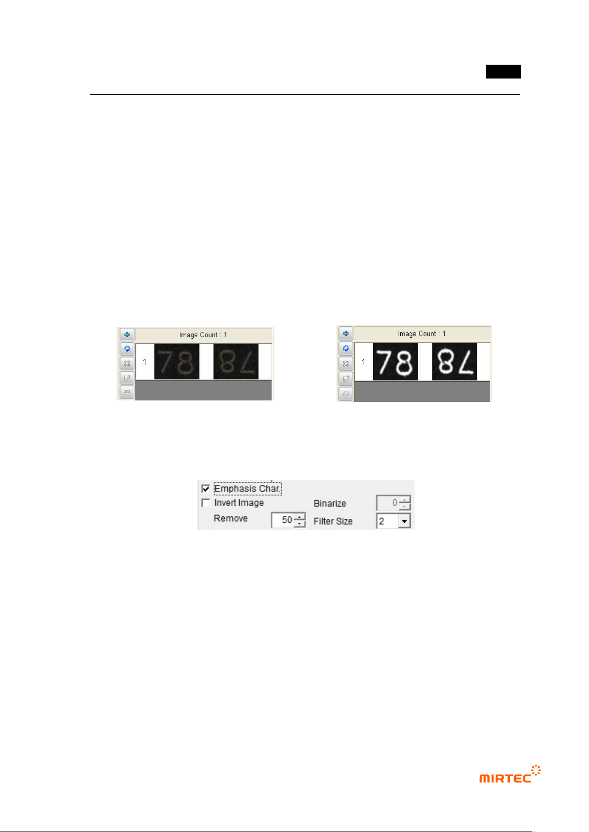
Character emphasis
- If character part of a component is not clear as shown in [Figure5-45], this function is to
clear character part by extracting only character part of a component through auto
binarization as shown in [Figure5-46].
[Figure 5-28 Pattern image before character
emphasis]
[Figure 5-29 Pattern image after character
emphasis]
Character emphasis parameter
[Figure 5-30 Character emphasis parameter]
Character emphasis
Set this option to use character emphasis.
Image reverse
In case of engraved character, this option is to reverse character emphasis image.
Noise removal
If character emphasis is selected, set size of max pixel that will be recognized as noise to
remove noise.
Filter size
If character emphasis is selected, filter size will adjust definition between background
image and character image.
MV-9 User Manual
5-32
Binarization
Manually set binarization value for more correct recognition after auto binarization of
character image. Select pattern model desired to be manually set to set binarization value.
Teaching method
i. Select mounting inspection algorithm and draw mounting image.
ii. Set character emphasis option.
[Figure 5-31 Before noise removal]
[Figure 5-32 After noise removal]
[Figure 5-33 Filter size - 1]
[Figure 5-34 Filter size - 2]
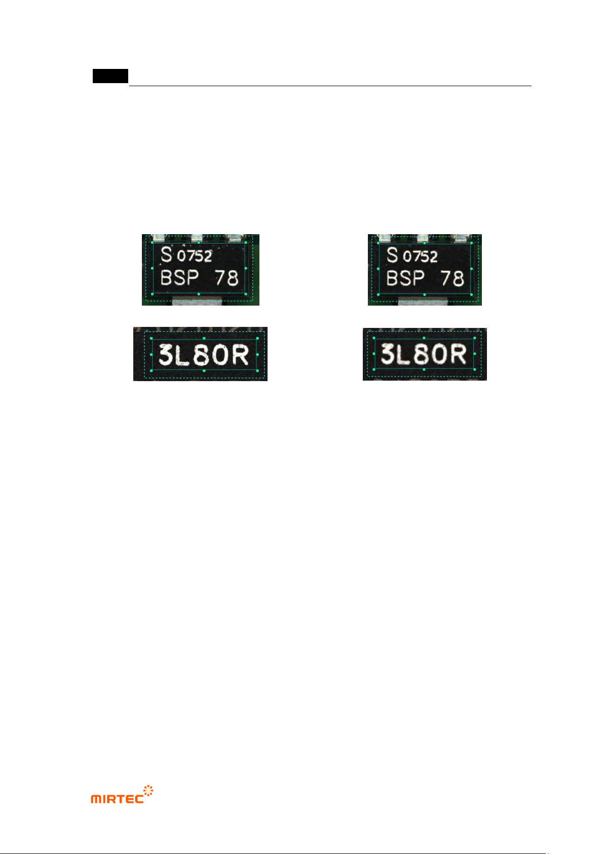
iii. As shown in [Figure5-48], in case there is noise besides character part, set noise
removal parameter to remove noise as shown in [Figure5-49].
iv. As shown in [Figure5-50], in case there is noise on image of character part itself,
set filter size to remove noise as shown in [Figure5-51].
v. In case of C chip or R chip, teaching must be done only for character part through
component edit mode.
Matching ratio
- Reference value judge inspection result value during PCB inspection. If it is lower than
reference, judge as defect and if it is higher than reference, judge as good.
Sensitivity
- Mainly, adjust sensitivity of mounting inspection for character inspection not to judge defect
component as normal according to fine sensitivity change of a component. It will be
activated when inspection type is normal mounting. Sensitivity can be set to max 3 stages.
Equally segment inspection area into the select region, and calculate each matching ratio.
Extract max matching ratio to compare it with reference matching ratio for good/defect
judgment.
Ignore deleted character
- This option is valid only when sensitivity is set to 3 regions. If more than 2 regions are
higher than reference matching ratio among 3 segmentation regions, judge as good.
-
错误!使用“开始”选项卡将 제목 2 应用于要在此处显示的文字。错误!使用“开始”选项卡将 제목 2 应用
于要在此处显示的文字。 .
5-33
Use max matching ratio
- This is to conduct pattern matching of all registered pattern images. Compare the highest
matching ratio with reference value to judge good/defect.
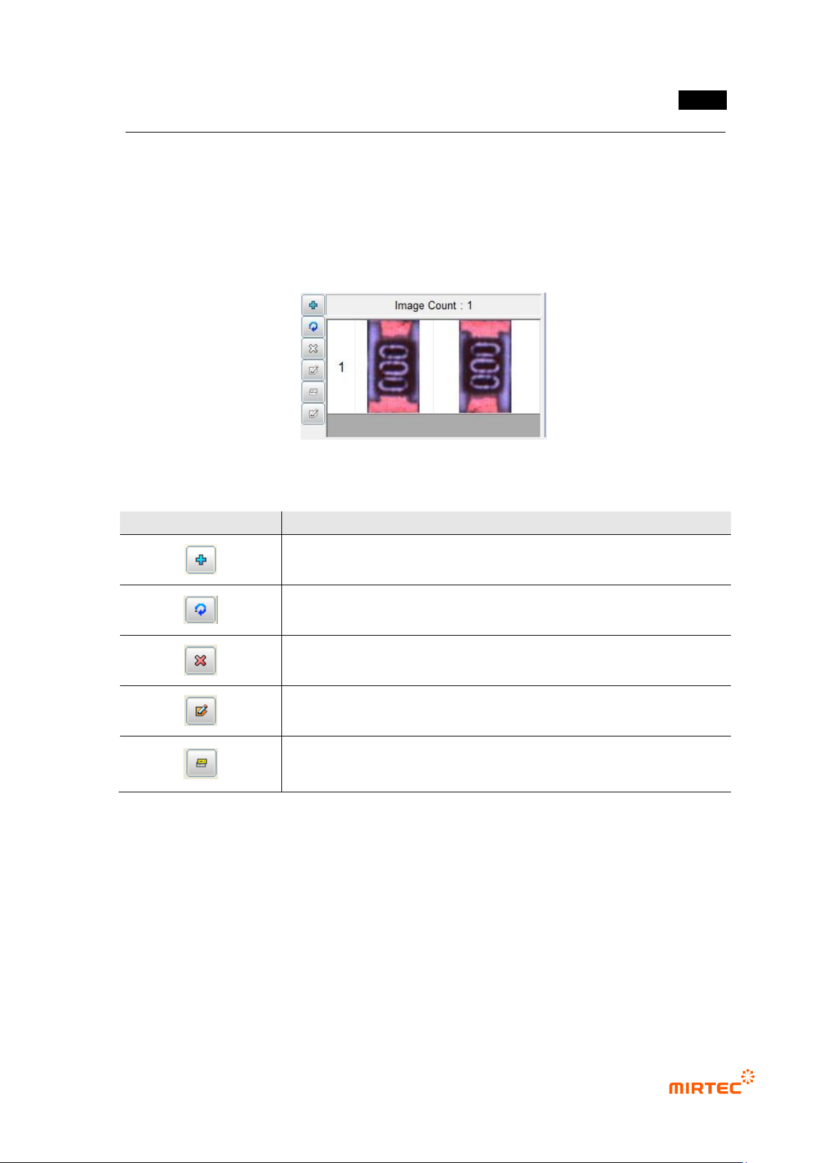
Pattern image screen
- This screen is to display pattern image registered during mounting inspection and chip
inspection.
[Figure 5-35 Pattern image screen]
[Table 5-2 Description of operating buttons]
icon
Name and Description
Current image add: add current image.
Current image refresh: re-image current image.
Current image delete: delete current image.
Mask image edit („Don‟t care region‟ setting): set unnecessary image
region to skip it during inspection.
Image synchronization: select specific pattern image and click
synchronization button to set „Don‟t care region‟ of a specific pattern at
once.
4) Inspection result in status screen
- To directly inspect mounting inspection window that completed teaching, select inspection
window and select „Inspect‟ in popup menu displayed by clicking right button of the mouse
or press enter key to start inspection. The following inspection result will be displayed in
inspection result screen on the bottom of the main screen after inspection.