MV-9_Chapter 5. Teaching.pdf - 第38页
MV -9 Use r Manual 5- 38 [T able 5-3 4 Bi narization methods of solder inspection window] S tatus Binarization image Description Hori zont al + vertical light image bi nar ize all level value below reference to black…
错误!使用“开始”选项卡将 제목 2 应用于要在此处显示的文字。错误!使用“开始”选项卡将 제목 2 应用
于要在此处显示的文字。 .
5-37
- Since soldering area is slope on PCB, light type of horizontal + vertical light ( ) and
image type of B (blue) for slope area are recommended. L (luminance) can be also
selected.
- If necessary, select horizontal - vertical ( ) or L (luminance). Vertical white light and
horizontal white light are used to create horizontal - vertical image.
Image type
- In case of horizontal + vertical light, select B or L for image type. In case of horizontal -
vertical, select L for image type.
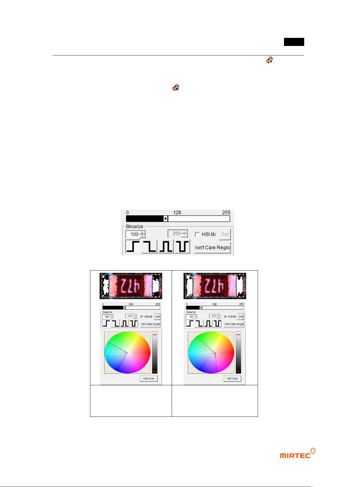
Binarization
- This means to express images in white (1) and black (0) for black and white image that is
express by 256 steps based on specific level value(binarization value).
- User can adjust desired color, saturation and luminance area for image type selected
using color map.
- To check binarized image in frame image screen, click <preview> button in „operating
buttons‟. [Table5-3] shows 4 binarization methods.
[Figure 5-38 Binarization value setting]
Binarization image in initial
status of color map
Binarization image after
adjusting color map and
binarization
[Figure 5-39 Binarization value setting]
MV-9 User Manual
5-38
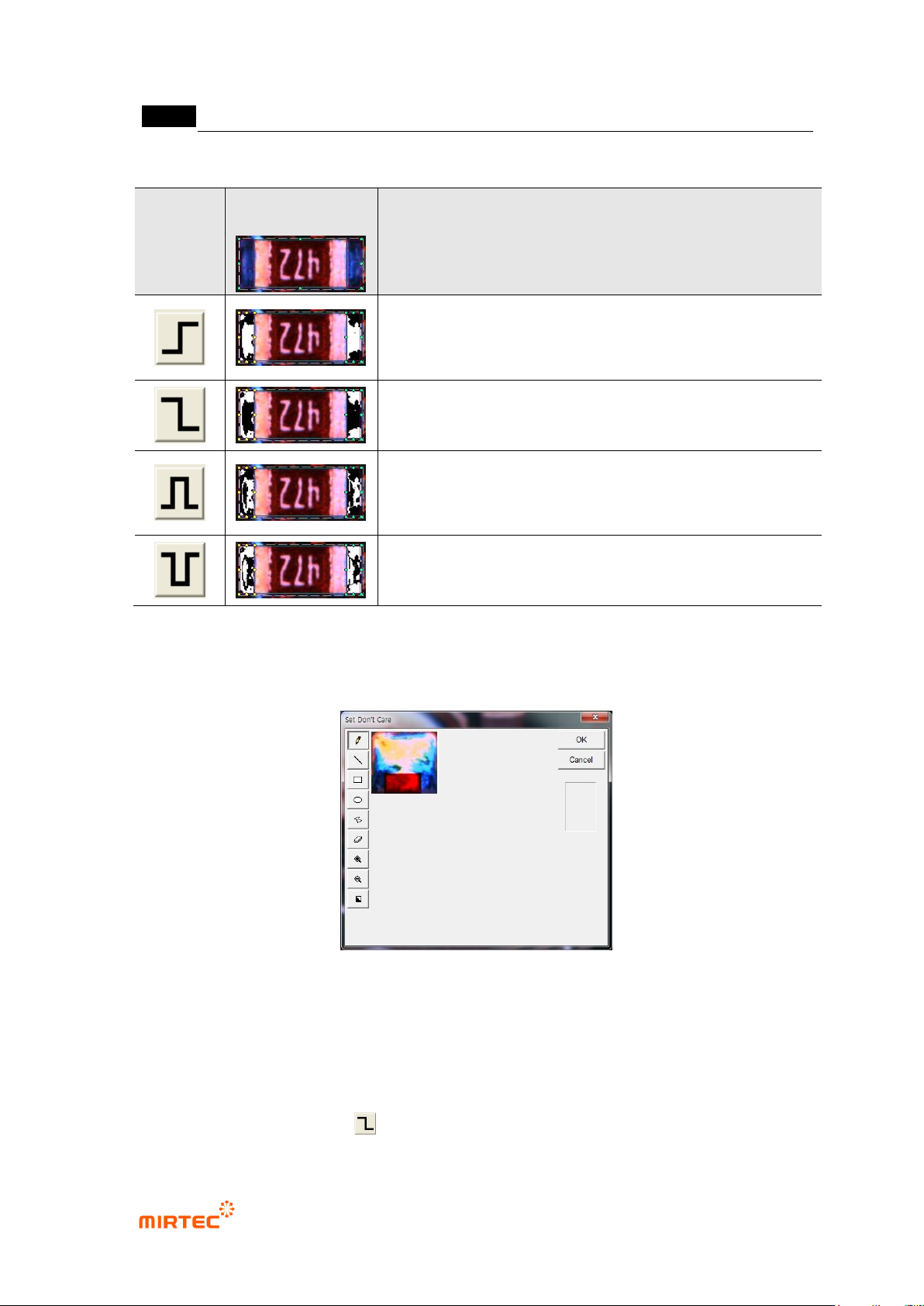
[Table 5-3 4 Binarization methods of solder inspection window]
Status
Binarization
image
Description
Horizontal + vertical light image
binarize all level value below reference to black (0), and all
level value over reference to white (1) based on one
binarization value (Ex: 100)
Binarize all level value below reference to white (1), and all
level value over reference to black (0) based on one
binarization value (Ex: 100).
Binarize all level value within reference range to white (1),
and all level value beyond range to black (0) based on2
binarization value (Ex: 100, 150).
Binarize all level value within reference range to black (0),
and all level value beyond range to white (1) based on2
binarization value (Ex: 100, 150).
‘Don’t care region’
- We can set „Don‟t care region‟ by drawing area in image in inspection window.
[Figure 5-40 ‘Don’t care region’ setting screen]
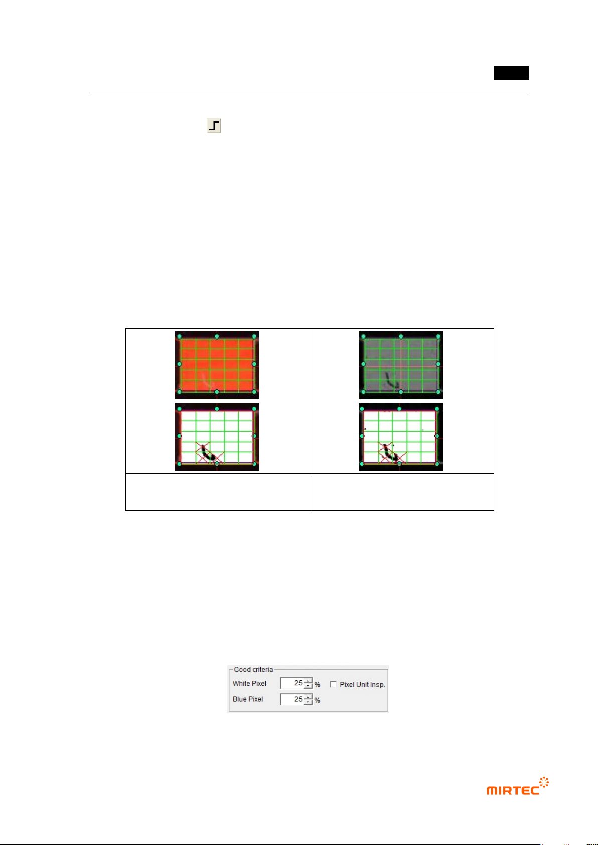
Use grid inspection
- Divide solder inspection window with grid and individually inspect each area to detect
solder ball or foreign material on pad.
- Since foreign material on a pad is brighter than pad in horizontal + vertical light, select B or
L for image type, select for binarization method, and adjust binarization value.
错误!使用“开始”选项卡将 제목 2 应用于要在此处显示的文字。错误!使用“开始”选项卡将 제목 2 应用
于要在此处显示的文字。 .
5-39
However, foreign material is darker than pad in vertical - horizontal light image, select L for
image type, select for binarization method and adjust binarization value.
- Enter grid value of width/height in width and height box to divide inside of solder into given
value and to conduct solder inspection for each area.
- Area set as „Don‟t care region‟ will be excluded from inspection.
- [Figure 5-58] shows solder window to which grid function is applied. Inspection will be
performed for each individual segmentation region.
- When grid inspection is used, if each individual grid is smaller than normal reference white
pixel ratio, it will be judged as defect and red X character will be displayed. If the lowest
value among inspection results of each individual grid than normal criteria, inspection
window will be judged as defect.
Defect detection used horizontal +
vertical light
Defect detection used vertical –
horizontal light
[Figure 5-41 Use of grid inspection]
Normal criteria
- White pixel ratio: ratio of reference matching value in white and imaged inspection window.
- Blue pixel ratio: ratio of reference matching value in blue and imaged inspection window.
However, this option can be used only when light type is color.
- Normal criteria must have value higher than reference matching value.
- Pixel unit inspection: unit of normal criteria will be changed to numbers.
[Figure 5-42 Normal criteria setting]