MV-9_Chapter 5. Teaching.pdf - 第52页
MV -9 Use r Manual 5- 52 [Figure 5- 56 Color inspection – arr ay in spection window creation screen] ② Parameter of color inspection – array in sp ection window - Inspection type Select color i nspection to i nspect so…
错误!使用“开始”选项卡将 제목 2 应用于要在此处显示的文字。错误!使用“开始”选项卡将 제목 2 应用
于要在此处显示的文字。 .
5-51
Min length: set min length to judge as defect. Crack of length below setting value
will be judged as normal. In case area is smaller than min area, conduct width
inspection. If it is smaller than setting value, judge as good.
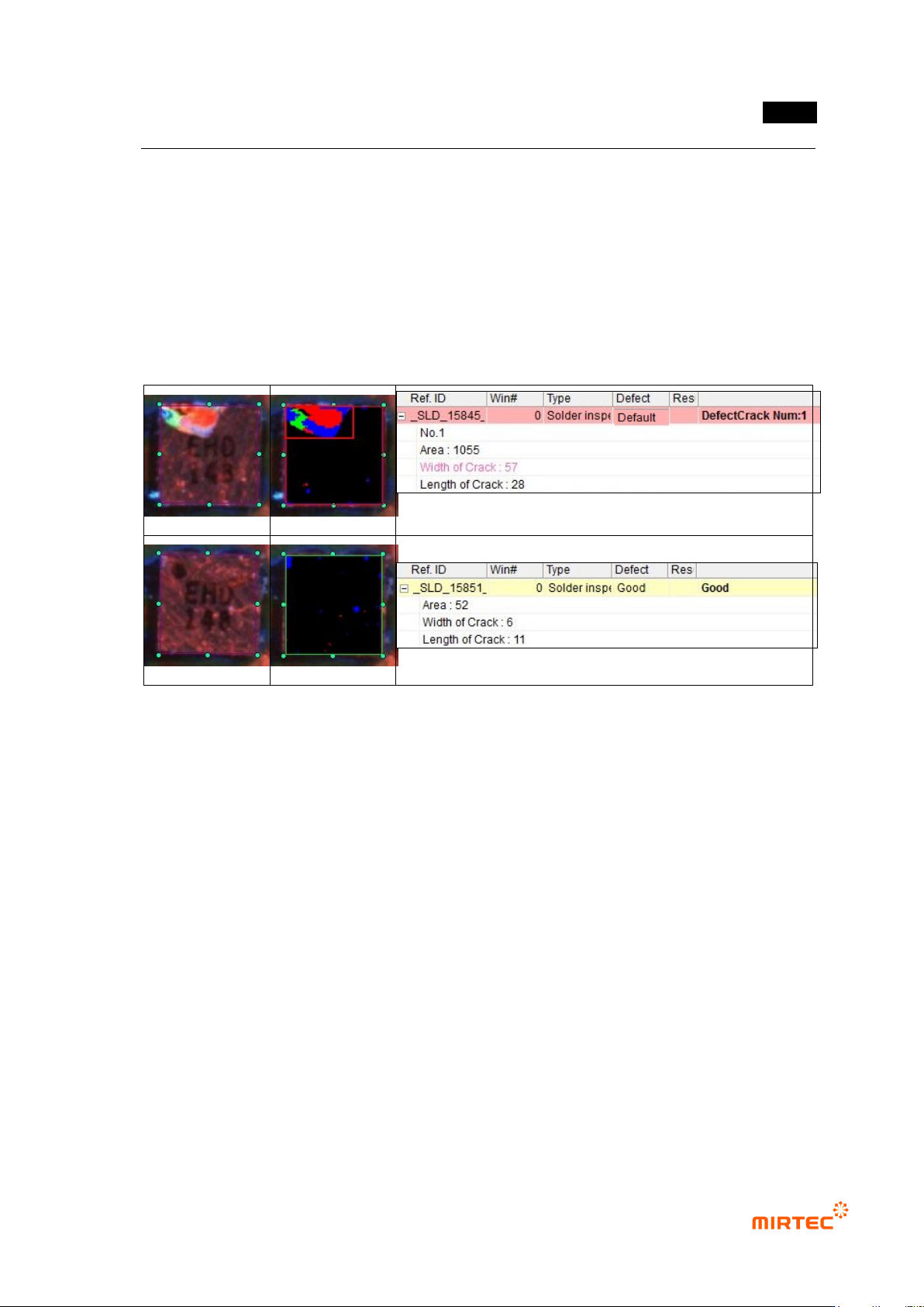
③ Color inspection – crack inspection result in status screen
- Area: area detected as defect (number of pixel).
- Width of Crack: width of area detected as crack defect.
- Length of Crack: length of area detected as crack defect.
[Figure 5-55 Crack inspection result in status screen]
2) Array inspection
① Teaching method
(a) Draw solder window in solder area in a component.
(b) Select color inspection and select „array‟ for component type.
(c) Select horizontal + vertical light for light type, and select A (all band = R+G+B) for image
type.
(d) Divide well red, green and blue area using color map and binarization.
(e) Set inspection criteria.
MV-9 User Manual
5-52
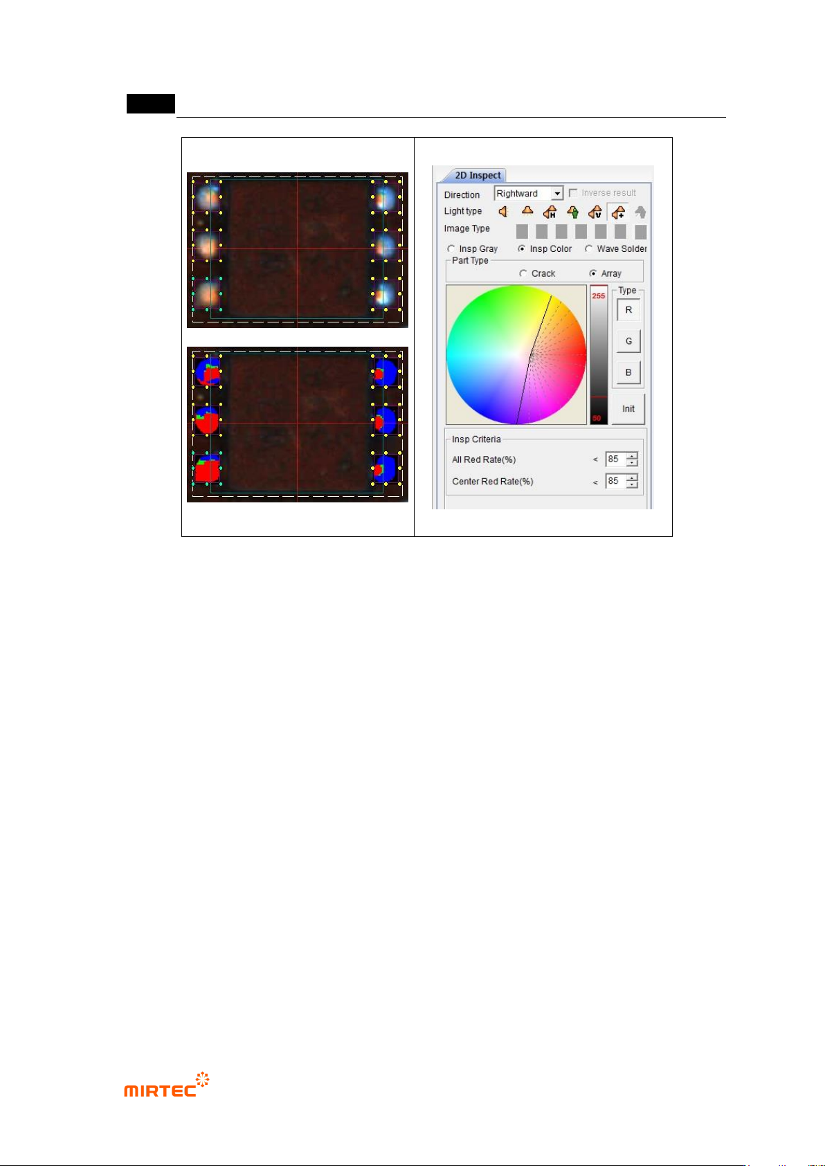
[Figure 5-56 Color inspection – array inspection window creation screen]
② Parameter of color inspection – array inspection window
- Inspection type
Select color inspection to inspect soldering defect (insufficient solder, lifted) of array
component.
- Component type
Array: conduct defect inspection for SMD of array resistance (Array Register) or
EMI filter shape.
- Color map and binarization
Adjust color and luminance (binarization) in color map to separate well red, green
and blue area.
- Inspection criteria
Total red ratio (%):
Stage 1: set ratio of red pixel in inspection window area. If red ratio is below
reference value, judge as good. If it is above reference value, judge as
insufficient solder. If defect is judged, inspection stage 2 and center red ratio
will not be inspected.
错误!使用“开始”选项卡将 제목 2 应用于要在此处显示的文字。错误!使用“开始”选项卡将 제목 2 应用
于要在此处显示的文字。 .
5-53
Stage 2: If stage 1 is normal and total of each RGB area is larger than total red
ratio in preview, judge as good. In this case, center red ratio inspection will not
be conducted.
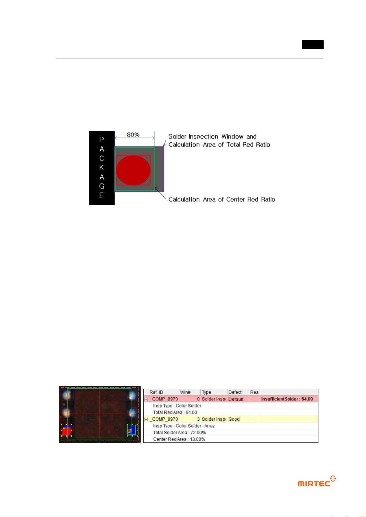
Center red ratio (%): set ratio of red area that exists within 80% range (80% area
from package exterior) of inspection window area. If red ratio is smaller than
reference value, judge as good. If red ratio is larger than reference value, judge as
lifted.
[Figure 5-57 Array solder inspection area]
③ Color inspection – array inspection result in status screen
- Inspection Type: inspection type.
- Total Red Area: ratio of red pixel within whole inspection window area (total red ratio
inspection stage 1).
- Total Solder Area: total pixel ratio of each RGB area within whole inspection window area
(total red ratio inspection stage 2).
- Red Area: ratio of red area in 80% range of inspection window comparing to whole
inspection window area. Inspection result of center red ratio.
- Lifted Array (Area, Red): judged as defect in center red ratio inspection, and area is total
pixel ratio of each RGB area (total red ratio inspection stage 2) result in total inspection
window. Red is calculated value of center red ratio.
- Insufficient Solder: judged as defect in total red ratio inspection. Ratio of red pixel within
whole inspection window area.