MV-9_Chapter 5. Teaching.pdf - 第73页
错误 ! 使用“开始” 选项卡将 제목 2 应用于要在此处显示的文字。 错误 ! 使用“开始”选项卡将 제목 2 应用 于要在此处显示的 文字。 . 5- 73 4) Position move inspection - Algo rithm to judge i f com pone nt edge i s in nor mal range b y detect com p onent edge , and Shift inspect…
MV-9 User Manual
5-72
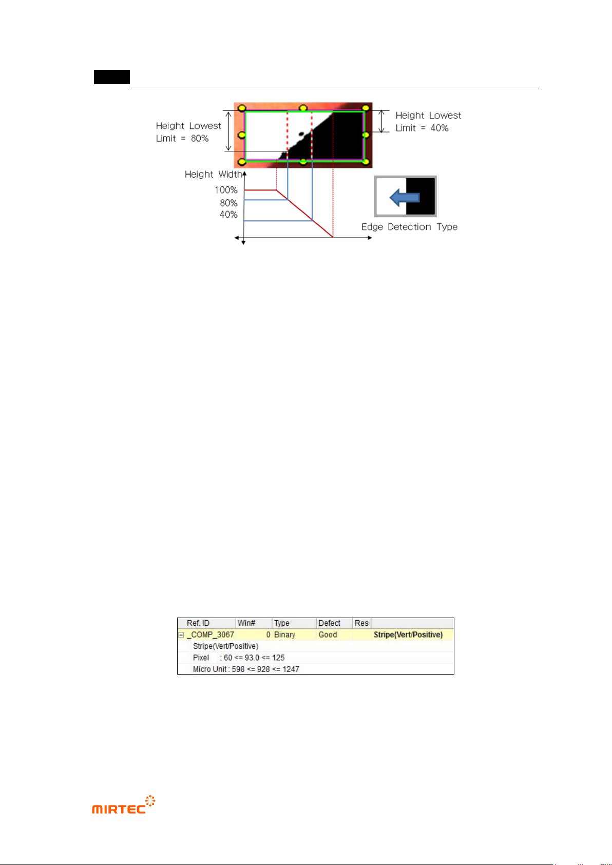
[Figure 5-78 Example of lowest height limit (%)]
Binarization
- Select auto or manual for binarization method.
- If „manual‟ is selected, adjust binarization value to well create edge in preview.
Size filtering
- This function is to apply filtering to remove noise from binarized image.
Normal criteria
- Min: Enter min value of stripe width to judge as good
- Current: Stripe width measured in inspection will be displayed.
- Max: Enter max value of stripe width to judge as good.
③ Inspection result in status screen
- Stripe (Vert/Positive): measurement of stripe width. Edge that finds „Vert‟ is vertical edge.
Positive means to find edge toward white area direction in black area.
- Pixel: stripe width expressed in number of pixel, min-current-max.
- Micro Unit: information displayed when real unit information view is selected in [Config.-
default setting-view], real length relevant to pixel.
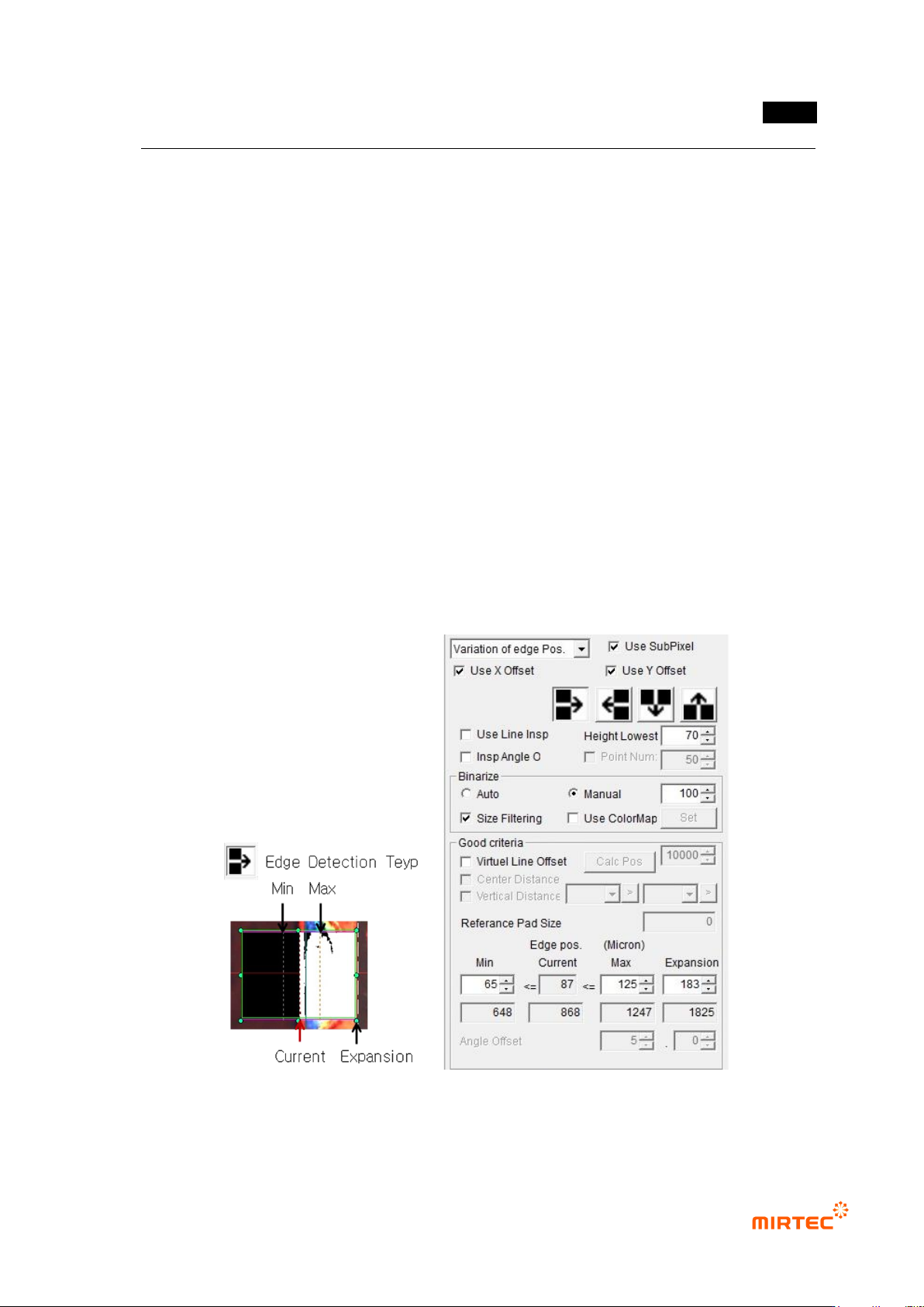
[Figure 5-79 inspection result]
错误!使用“开始”选项卡将 제목 2 应用于要在此处显示的文字。错误!使用“开始”选项卡将 제목 2 应用
于要在此处显示的文字。 .
5-73
4) Position move inspection
- Algorithm to judge if component edge is in normal range by detect component edge, and
Shift inspection can be conducted.
① Teaching method
(a) Draw binary inspection window in inspection area, and select position move inspection
for inspection type.
(b) Select detection type.
(c) Enter width lowest limit.
(d) For angle inspection, check at angle inspection.
(e) Set binarization method and binarization value checking preview image.
(f) If there is noise, select size filtering.
(g) In case of binarization using color information, select color map. Click setting button to
adjust color, saturation and luminance checking preview image.
(h) Enter normal criteria.
[Figure 5-80 Teaching example of position move inspection window]
MV-9 User Manual
5-74
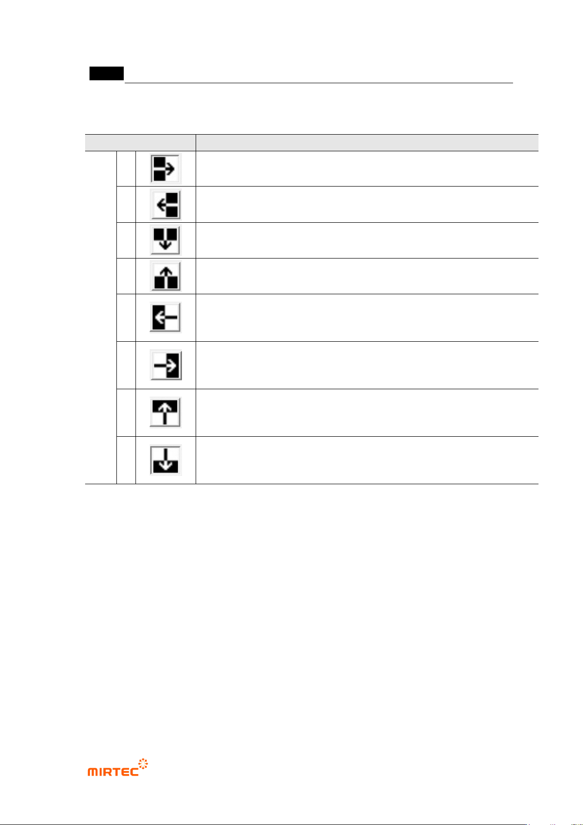
[Table 5-6 Binary inspection – position move boundary line detection type]
Detection type
Description
Bou
ndar
y
line
dete
ction
type
1
Search boundary line from left to right, and detect Positive (change from
black to white) boundary line.
2
Search boundary line from right to left, and detect Positive boundary line.
3
Search boundary line from up to down, and detect Positive (change from
black to white) boundary line.
4
Search boundary line from down to up, and detect Positive (change from
black to white) boundary line.
5
Click inspection type No 1 one more time to convert detection type.
Search boundary line from right to leftward, and detect Negative (change
from white to black) boundary line.
6
Click inspection type No 2 one more time to convert detection type.
Search boundary line from left to rightward, and detect Negative boundary
line.
7
Click inspection type No 3 one more time to convert detection type.
Search boundary line from down to up, and detect Negative (change from
black to white) boundary line.
8
Click inspection type No 4 one more time to convert detection type.
Search boundary line from up to down, and detect Negative (change from
black to white) boundary line.
① Parameter description
Use SubPixel
Basically, use binary image for inspection that uses edge among detailed items of binary
inspection. However, in case of detection of more precise edge using black and white
image, check at „UseSubPixel‟.
Detection type
Select detection type of same shape referring to preview image.
Arrow direction is the direction to search edge. Start direction of the arrow is the
reference point of boundary line position and normal range.
Use line inspection