MV-9_Chapter 5. Teaching.pdf - 第78页
MV -9 Use r Manual 5- 78 5) Solder ball inspection - This inspection m etho d is t o detect so lder ball on pad or substrate . Basic princ i ple is to separate solder ball inspection target area an d to detect solder bal…
错误!使用“开始”选项卡将 제목 2 应用于要在此处显示的文字。错误!使用“开始”选项卡将 제목 2 应用
于要在此处显示的文字。 .
5-77
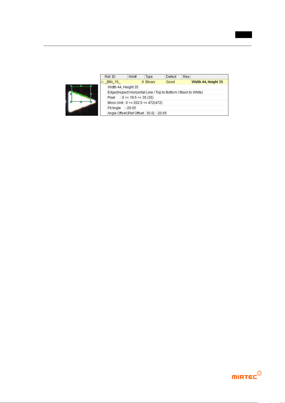
Angle inspection using SubPixel
- If SubPixel is used, it segment inspection area. Position of boundary line detected in
segmented area will be displayed in the screen.
[Figure 5-84 Angle inspection result using SubPixel]

MV-9 User Manual
5-78
5) Solder ball inspection
- This inspection method is to detect solder ball on pad or substrate. Basic principle is to
separate solder ball inspection target area and to detect solder ball on the area. In other
words, if white area exists in both of 2 areas, judge as solder ball.
- For pad and bridge binarization, we separate solder ball inspection target area and
separate solder ball area for solder binarization.
- The followings are general characteristics of image of solder ball according to light.
Margin of solder ball appears in blue in horizontal + vertical light image and central
part of solder ball appears in red.
If white light is used, margin of solder ball appears in horizontal light, and central
part of solder ball appears in vertical light.
① Teaching method
(a) Draw binary inspection window in inspection area and select solder ball inspection for
inspection type.
(b) Select preview in operation window and select preview – pad for parameter.
(c) Select light type and image type for pad/Bridge binarization.
(d) If there is other inspection window in inspection area, check at „exclude other inspection
area‟.
(e) Set binarization method and binarization value checking image.
(f) To remove noise, adjust size filtering and space filling value.
(g) Select preview – solder for parameter.
(h) Select light type and image type for Solder binarization.
(i) Set binarization method and binarization value checking image.
(j) To reverse an image, check image reverse.
(k) Set „Don‟t care region‟.
(l) Enter normal criteria. Basically, we conduct ratio inspection. In case of inspection using
number of white pixel, check white pixel inspection.
错误!使用“开始”选项卡将 제목 2 应用于要在此处显示的文字。错误!使用“开始”选项卡将 제목 2 应用
于要在此处显示的文字。 .
5-79
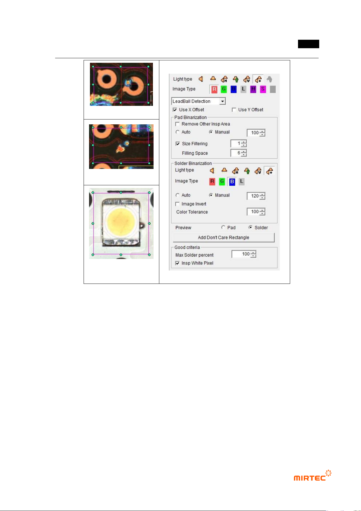
solder ball on pad
solder ball on substrate
solder ball on LED
substrate
[Figure 5-85 Teaching example of solder ball inspection window]
① Parameter description
Pad/Bridge binarization
- Light type and image type
Use parameter in common parameter window for light type and image type for pad
binarization. In general, select B type or L of horizontal + vertical light. Sometimes,
select L type of vertical light.
- Exclude other inspection area
Check at this option if inspection area that completed teaching and other inspection
window is overlapped. other inspection window will be regarded as „Don‟t care
region‟.
- Binarization
Set auto or manual for binarization. Set binarization value checking preview-pad
during manual setting.