MV-9_Chapter 5. Teaching.pdf - 第92页
MV -9 Use r Manual 5- 92 After boundary noise removal Af ter m in a rea limit [Figure 5- 98 Normal criteria application example] [Figure 5- 99 Preview image for tap insp ection] ② Inspectio n r esult in status screen - D…
错误!使用“开始”选项卡将 제목 2 应用于要在此处显示的文字。错误!使用“开始”选项卡将 제목 2 应用
于要在此处显示的文字。 .
5-91
Binary image
After 1 time application of
opening
After 1 time application of
expansion
[Figure 5-96 morphology open and expansion apply example]
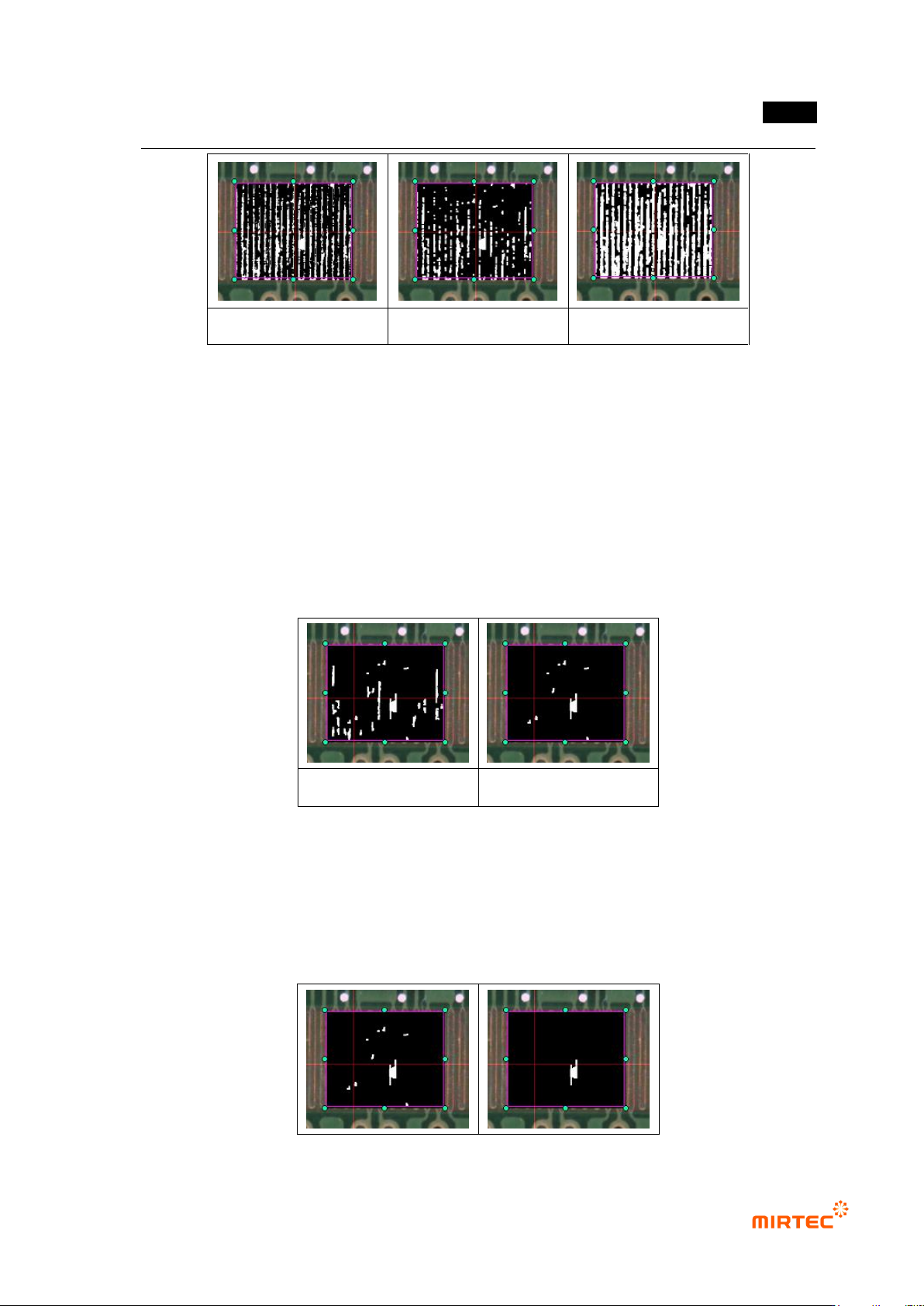
- Tap boundary noise removal
In many cases, exterior boundary line of tap area appears bright by horizontal light,
and this will cause false defect during inspection.
Characteristic of boundary line is thin and long toward vertical or horizontal
direction by binarization. Hence, firstly, remove boundary line noise using width and
length.
Max width means max thickness of boundary line to be removed, and min length
means min length of boundary line.
Before boundary noise
removal
After boundary noise
removal
[Figure 5-97 application example of boundary line noise removal]
Normal criteria
- Enter min area of white pixel region that is judged as defect in binarization image. white
area that is larger than this value will be detected as defect.
- Only white area (defect) larger than min area will be displayed in preview image.
MV-9 User Manual
5-92
After boundary noise
removal
After min area limit
[Figure 5-98 Normal criteria application example]
[Figure 5-99 Preview image for tap inspection]
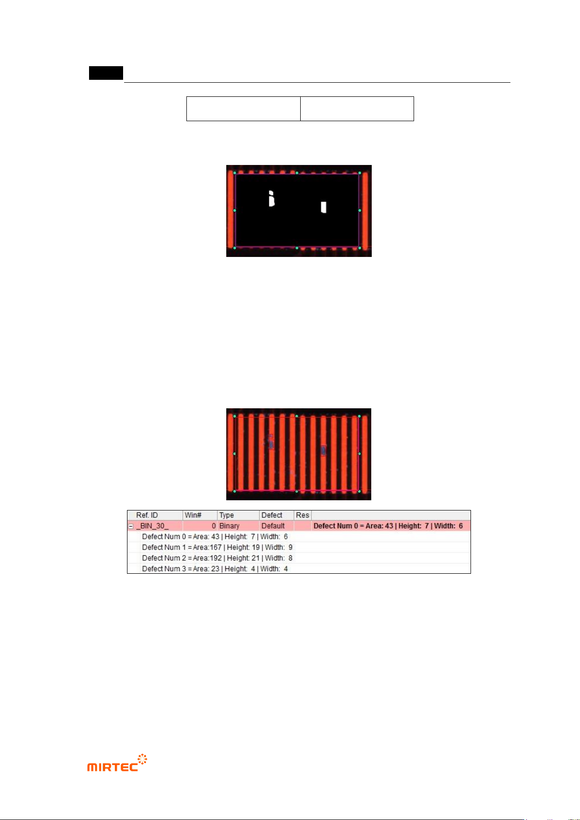
② Inspection result in status screen
- Defect Num X: No allotted to white area detected as defect.
- Area: number of pixel (area) of white area detected as defect.
- Height: height of rectangle drawn in white area detected as defect.
- Width: width of rectangle drawn in white area detected as defect.
[Figure 5-100 Multiple tap inspection result]

错误!使用“开始”选项卡将 제목 2 应用于要在此处显示的文字。错误!使用“开始”选项卡将 제목 2 应用
于要在此处显示的文字。 .
5-93
8) Eccentricity inspection
- This inspection algorithm is to inspect position of pin located in the center on component
shaped like a BNC connector based on outer circle. calculate the distance after searching
center position of outer circle and inner circle.
① Teaching method
(a) Select preview in operation window, and select preview-outside among eccentricity
inspection parameter.
(b) Select light type and image type to detect outer circle.
(c) Manually select binarization method in outer circle, and set binarization value for good
separation of outer circle to be detected
(d) Adjust radius according to outer circle to be detected, and adjust search range.
(e) Select type of boundary line to be detected in each search range of outer circle.
(f) Select preview-inside, and light type and select image type to detect inner circle.
(g) Manually select binarization method in inner circle, and set binarization value for good
separation of inner circle to be detected
(h) Adjust radius according to inner circle to be detected, and adjust search range.
(i) Select type of boundary line to be detected in each search range of inner circle.
(j) Conduct trial inspection to display radius of detected outer circle and inner circle in
current. Set allowable range of radius of detected circle in the range.
(k) Enter normal criteria in pixel unit for distance between detected outer circle and outer
circle center.