Nordson_EFD_Rhino_SD2_XD2_Operating Manual.pdf - 第11页
Rhino SD2/XD2 Pumps 7 Part 1073520-12 E 2013 Nordson Corporation Repair This section only covers the procedures necessary to perform shop repairs. Refer to the Rhino SD2/XD2 Frames manual for procedures on removing the p…
Rhino SD2/XD2 Pumps
6
E 2013 Nordson Corporation
Part 1073520-12
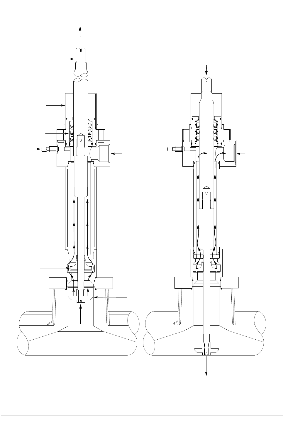
PLUNGER
SOLVENT CHAMBER
PACKING GLAND
BLEED VALVE
LOWER CHECK
FOLLOWER PLATE
SHOVEL
UP
DOWN
STROKE
STROKE
OUTPUT PORT
MATERIAL DOES
NOT FLOW DURING
THE UPSTROKE.
OUTPUT PORT
MATERIAL FLOW
S
DURING THE
DOWN STROKE.
Figure 4 Stainless Steel Single-Acting Hydraulic Section
Rhino SD2/XD2 Pumps
7
Part 1073520-12
E 2013 Nordson Corporation
Repair
This section only covers the procedures necessary to
perform shop repairs. Refer to the Rhino SD2/XD2
Frames manual for procedures on removing the pump
from the bulk unloader.
WARNING: Allow only qualified personnel to
perform the following tasks. Follow the safety
instructions in this document and all other related
documentation. Review the following:
S Relieve all pressure to the pump before
performing repair procedures.
S Read and understand this entire section
before repairing this equipment. Some
repairs can be made without breaking down
the pump.
S If necessary, contact a local Nordson
representative with questions about
these procedures.
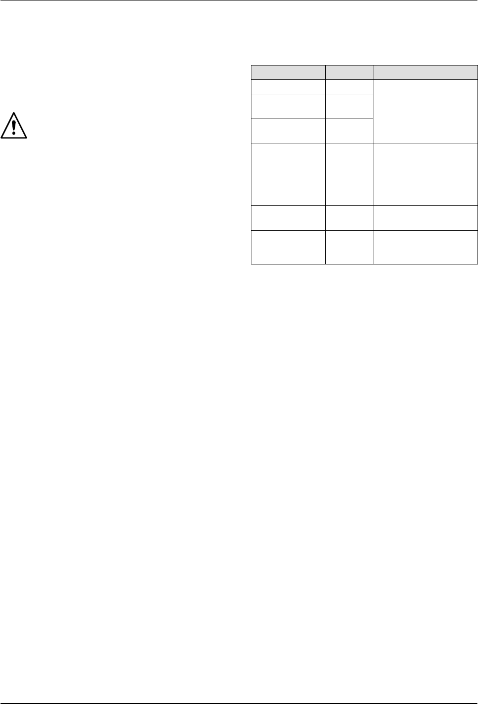
Consumable Items
Keep the following on hand when repairing the pump.
Item Part Application
Never-Seez 900344
Apply to threads of
applicable parts.
Threadlock
Adhesive
900464
Pipe/Thread
Sealant
900481
TFE Grease 1031834
(1-gal.)
or
900349
(0.75 oz)
Lubricate air motor
components.
O-Ring
Lubricant
900223 Lubricate hydraulic
section components.
Mobil SHC 634 156289 Lubricate stainless
steel hydraulic section
components.

Rhino SD2/XD2 Pumps
8
E 2013 Nordson Corporation
Part 1073520-12
Break Down the Pump
See Figure 5 and perform the desired procedure.
Repairs to the Hydraulic Section
1. Remove the screws (6) securing the coupling
halves (7) to the floating coupling shaft (2) and
plunger rod (3).
2. Remove the nuts (4) securing the hydraulic
section (5) to the connecting rods (8).
3. Remove the hydraulic section from the
pump assembly.
4.
TEMPERATURE CONDITIONED PUMPS: Remove the
cover (9) from the hydraulic section.
5. Refer to the Hydraulic Section procedures to perform
the desired repairs.
Repairs to the Air Motor
1. Remove the screws (6) securing the coupling
halves (7) to the floating coupling shaft (2) and
plunger rod (3).
2. Remove the nuts (4) securing the hydraulic
section (5) to the connecting rods (8).
CAUTION: The air motor is heavy. Have an
assistant help with removing the air motor from
the hydraulic section.
3. Remove the air motor (1) from the hydraulic
section (5). Remove the connecting rods (8) from
the air motor (1).
4. Refer to the Air Motor procedures to perform the
desired repairs.