Nordson_EFD_Rhino_SD2_XD2_Operating Manual.pdf - 第14页
Rhino SD2/XD2 Pumps 10 E 2013 Nordson Corporation Part 1073520-12 Standard and T emperature Conditioned Hydraulic Sections The following paragraphs provide procedures for repairing a standard or temperature conditioned h…
Rhino SD2/XD2 Pumps
9
Part 1073520-12
E 2013 Nordson Corporation
2
4
5
6
1
3
8
7
7
9
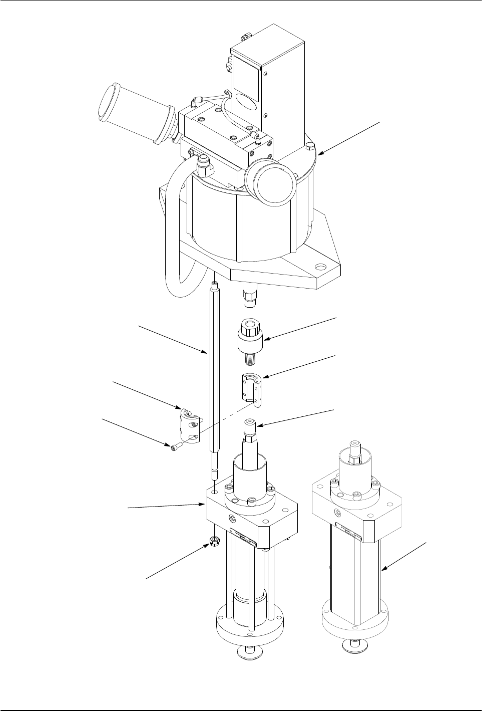
Figure 5 Typical Air Motor and Hydraulic Section

Rhino SD2/XD2 Pumps
10
E 2013 Nordson Corporation
Part 1073520-12
Standard and Temperature
Conditioned Hydraulic Sections
The following paragraphs provide procedures for
repairing a standard or temperature conditioned hydraulic
section.
Disassemble the Hydraulic Section
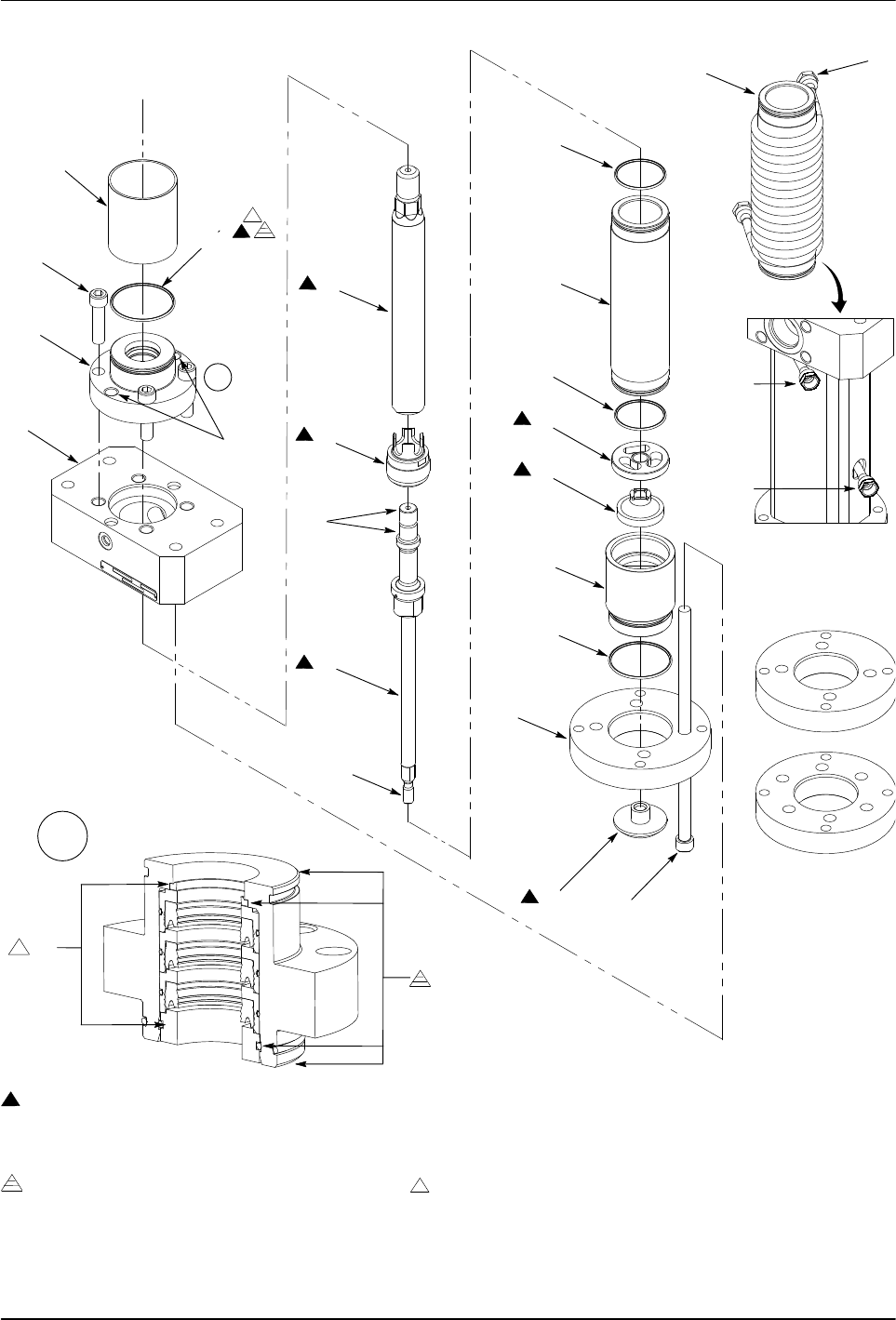
1. See Figure 6. Remove the solvent chamber (1) and
the O-ring (2) from the packing gland (4). Discard
the O-ring.
NOTE: Packing glands have either 4 or 6 screws.
2. Perform the following:
a. Remove the screws (3) from the packing
gland (4). Insert two screws into the threaded
holes (20) as shown.
b. Alternate tightening the screws to remove the
packing gland (4) from the upper pump body (5).
3. Remove the shovel adapter (18) from the rod
assembly (10).
NOTE: Hydraulic sections have either 4 or 6 screws that
secure the cylinder assembly to the upper pump body.
4. Remove the screws (19) securing the cylinder
assembly and follower plate housing (17) to the upper
pump body (5). Remove the follower plate housing.
5. Remove the bottom housing (15), O-ring (16), lower
check plate (14), and spacer (13). Discard
the O-ring.
6. Remove the cylinder housing (12) from the upper
pump body (5). Remove and discard the O-rings (11)
from the cylinder housing.
TEMPERATURE CONDITIONED SECTIONS: It is not
necessary to remove the coil (25) unless it or the
cylinder housing needs to be replaced.
7. Using either an arbor press or hydraulic press, push
the plunger rod (6) out of the cylinder housing (12).
8. Remove the rod assembly from the plunger rod (6).
Remove and discard the piston assembly (9).
9. Clean the parts with a compatible solvent. Refer to
Table 4 in the Specifications section for wetted
component materials.
10. Inspect parts for nicks, scratches, wear, and damage.
Replace parts if necessary.
11. Rebuild the packing gland (4) if necessary. Refer to
the Rebuild the Packing Gland procedure in this
section for procedures.
Assemble the Hydraulic Section
1. See Figure 6. Apply O-ring lubricant (23) to the
packing gland O-ring (2) and the packing
gland I.D. (21).
2. Install the packing gland (4) into the upper pump
body (5).
3. Apply Never Seez (22) to the threads of the
screws (3). Install the screws into the packing
gland (4) and tighten to 102−108 Nm (75−80 ft-lb).
4.
TEMPERATURE CONDITIONED SECTIONS: Install the coil
(25) onto the cylinder housing (12) if necessary.
5. Apply O-ring lubricant (23) to the O-rings (11) and I.D.
of the cylinder housing (12). Install the O-rings onto
the cylinder housing. Install the cylinder housing onto
the upper pump body (5).
6. Assemble the plunger rod assembly:
a. Install the piston assembly (9) onto the rod
assembly (10).
b. Apply Never Seez (22) to the upper threads and
pilot of the rod assembly. Connect the rod
assembly to the plunger rod (6) and tighten to
272−298 Nm (200−220 ft-lb).
c. Apply a thin coat of O-ring lubricant (23) to
the plunger rod, piston assembly, and the
rod assembly.
7. Using either an arbor press or hydraulic press, install
the plunger rod assembly through the cylinder
housing (12) and packing gland (4).
8. Install the spacer (13) and lower check plate (14)
onto the rod assembly.
9. Install the bottom housing (15) onto the cylinder
housing (12). Apply O-ring lubricant (23) to the
O-ring (16) and install it onto the bottom housing.
10. Install the follower plate housing (17) onto the bottom
housing (15).
NOTE: Hydraulic sections have either 4 or 6 screws that
secure the cylinder assembly to the upper pump body.
11. Apply Never Seez (22) to the threads of the
screws (19). Perform the following:
a. Install the screws through the follower plate
housing (17) and into the upper pump body (5).
b. Hand-tighten two opposing screws at the same
time until the follower plate housing, bottom
housing, and cylinder housing (12) are secured
to the upper pump body (5). Hand-tighten the
remaining screws as shown.
c. After performing step 10b, simultaneously tighten
each screw 1/8 turn at a time in the sequence
shown to 102−108 Nm (75−80 ft-lb).
12. Apply threadlock adhesive (24) to the lower threads
of the rod assembly. Install the shovel adapter (18)
to the rod assembly and tighten to
75−81 Nm (55−60 ft-lb).
13. Install the solvent chamber cup (1) onto the
packing gland (4).
Rhino SD2/XD2 Pumps
11
Part 1073520-12
E 2013 Nordson Corporation
1
2
3
4
5
6
9
10
12
11
13
14
15
16
17
18
19
11
PARTS ARE INCLUDED IN THESE KITS:
5.8 CUBIC INCH PACKING GLAND SERVICE KIT 1104726
8.1 CUBIC INCH PACKING GLAND SERVICE KIT 1104731
PARTS ARE INCLUDED IN THESE KITS:
SD2 5.8 CUBIC INCH DRIVE TRAIN SERVICE KIT 1105066
XD2 5.8 CUBIC INCH DRIVE TRAIN SERVICE KIT 1105065
SD2 8.1 CUBIC INCH DRIVE TRAIN SERVICE KIT 1105067
XD2 8.1 CUBIC INCH DRIVE TRAIN SERVICE KIT 1105068
20
A
22
22
23
23
23
23
23
23
22
24
23
23
A
PARTS ARE INCLUDED IN THESE KITS:
5.8 CUBIC INCH PACKING GLAND INTERNAL PARTS SERVICE KIT 1081134
8.1 CUBIC INCH PACKING GLAND INTERNAL PARTS SERVICE KIT 1081135
21
23
SEQUENCES
2
3
4
1
TORQUE
2
3
4
1
5
6
12
23
25
INLET
OUTLET
PORT
PORT
Figure 6 Standard Hydraulic Section Repairs