Nordson_EFD_Rhino_SD2_XD2_Operating Manual.pdf - 第17页
Rhino SD2/XD2 Pumps 13 Part 1073520-12 E 2013 Nordson Corporation SCRAPER RING SHARP EDGE DOWN 3 1 2 4 8 6 P ACKING GLAND HOUSING 5 BRASS SEAL RET AINER OR BACKUP W ASHER SHOWN SLIGHTL Y BELOW P ACKING GLAND HOUSING 7 9 …

Rhino SD2/XD2 Pumps
12
E 2013 Nordson Corporation
Part 1073520-12
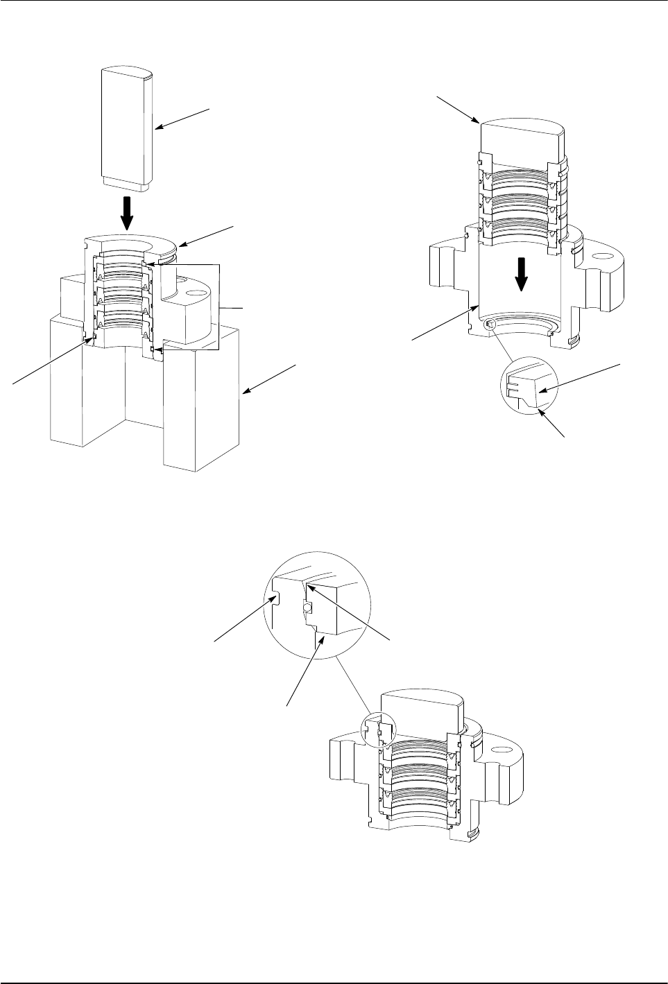
Rebuild the Packing Gland
NOTE: This procedure requires the use of either a
hydraulic or an arbor press to remove the internal parts
of the packing gland.
1. See Figure 7. Place the packing gland housing (2)
on a fixture (5) with the solvent cup end facing up.
NOTE: During removal of the internal parts, the retainer
groove will break the O-ring (4).
2. Insert the removal arbor (1) into the packing
gland housing. Using the press, push out
the internal parts (3).
3. Thoroughly clean the packing gland housing in a
compatible solvent to remove all sealant material and
O-ring debris.
4. Coat the bore (8) of the packing gland housing with
O-ring lubricant (9).
5. Insert the scraper or retaining ring (7), sharp edge
down, into the the packing gland (2).
6. Using the insertion tool (6) and press, insert the new
internal parts into the packing gland housing (2).
Make sure that the brass seal retainer or backup
washer (10) is flush or slightly below the packing
gland housing as shown.
Rhino SD2/XD2 Pumps
13
Part 1073520-12
E 2013 Nordson Corporation
SCRAPER RING
SHARP EDGE DOWN
3
1
2
4
8
6
PACKING GLAND HOUSING
5
BRASS SEAL RETAINER OR
BACKUP WASHER SHOWN SLIGHTLY
BELOW PACKING GLAND HOUSING
7
9
10
Figure 7 Typical Packing Gland Internal Parts Replacement

Rhino SD2/XD2 Pumps
14
E 2013 Nordson Corporation
Part 1073520-12
Stainless Steel Hydraulic Section
The following paragraphs provide procedures for
repairing the stainless steel hydraulic section.
Disassemble the Hydraulic Section
1. See Figure 8. Remove the solvent chamber (1) and
the O-ring (2) from the packing gland (5). Discard
the O-ring.
2. Remove the packing gland assembly:
a. Remove the screws (3) from the collar (4). Insert
two screws into the threaded holes (9) as shown.
b. Alternate tightening the screws to remove the
packing gland assembly from the upper
pump body (8).
c. Loosen the set screws (6) and remove the
packing gland (5) from the collar (4).
d. Remove the fittings (7) from the packing gland.
3. Remove the shovel adapter (20) from the shovel
rod (12).
4. Remove the screws (21) securing the cylinder
assembly and follower plate housing (19) to the upper
pump body (8). Remove the follower plate housing.
5. Remove the bottom housing (17), O-ring (18), lower
check plate (16), and spacer (15). Discard
the O-ring.
6. Remove the cylinder housing (13) from the upper
pump body (8). Remove and discard the O-rings (14)
from the cylinder housing.
7. Remove the shovel rod (12) from the plunger
rod (11).
8. Clean the parts with a compatible solvent. Refer to
Table 4 in the Specifications section for wetted
component materials.
9. Inspect parts for nicks, scratches, wear, and damage.
Replace parts if necessary.
Assemble the Hydraulic Section
1. See Figure 8. Apply threadlock adhesive (10) to the
threads of the fittings (7). Install the fittings into the
packing gland (5) and tighten securely.
2. Apply Mobil SHC 634 lubricant (22) to the packing
gland O-ring (2) and the I.D. of the packing gland (5).
3.
Install the upper collar (4) onto the packing gland (5).
Tighten the set screws (6) until they make contact with
the packing gland. Do not over tighten the set screws.
4. Install the packing gland assembly onto the body (8).
5. Apply Never Seeze (23) to the threads of the
screws (3). Install the screws into the packing gland
assembly and tighten to 102−108 Nm (75−80 ft-lb).
6. Apply Mobil SHC 634 lubricant (22) to the cylinder
housing O-rings (14). Install the O-rings onto the
cylinder housing (13). Install the cylinder housing
onto the upper pump body (8).
7. Assemble the plunger rod assembly:
a. Apply Never Seez (23) to the upper threads and
pilot of the shovel rod (12).
b. Connect the shovel rod to the plunger rod (11)
and tighten to 272−298 Nm (200−220 ft-lb).
c. Apply a thin coat of Mobil SHC 634 lubricant (22)
to the plunger rod (11) and the shovel rod (12).
8. Using either an arbor press or hydraulic press, install
the plunger rod assembly into the cylinder housing
(13) and packing gland (5).
9. Install the spacer (15) and lower check plate (16)
onto the rod assembly.
10. Install the bottom housing (17) onto the cylinder
housing (13). Apply Mobil SHC 634 lubricant (22) to
the O-ring (18) and install it onto the bottom housing.
11. Install the follower plate housing (19) onto the bottom
housing (17).
12. Apply Never Seez (23) to the threads of the
screws (21). Perform the following:
a. Install the screws through the follower plate
housing (19) and into the upper pump body (8).
b. Hand-tighten two opposing screws at the same
time until the follower plate housing, bottom
housing (17), and cylinder housing (13) are
secured to the upper pump body (8).
Hand-tighten the remaining screws as shown.
c. After performing step 12b, simultaneously tighten
each screw 1/8 turn at a time in the sequence
shown to 102−108 Nm (75−80 ft-lb).
13. Apply Never Seez (23) to the lower threads of the rod
assembly. Install the shovel adapter (20) to the rod
assembly and tighten to 75−81 Nm (55−60 ft-lb).
14. Install the solvent chamber cup (1) onto the
packing gland assembly.