Nordson_EFD_Rhino_SD2_XD2_Operating Manual.pdf - 第19页
Rhino SD2/XD2 Pumps 15 Part 1073520-12 E 2013 Nordson Corporation 1 2 3 4 8 11 12 23 13 14 15 16 17 18 19 20 21 22 22 22 5 7 6 22 22 23 23 14 22 P ARTS ARE INCLUDED IN THIS KIT : XD 2 8.1 CUBIC INCH ST AINLESS STEEL P AC…

Rhino SD2/XD2 Pumps
14
E 2013 Nordson Corporation
Part 1073520-12
Stainless Steel Hydraulic Section
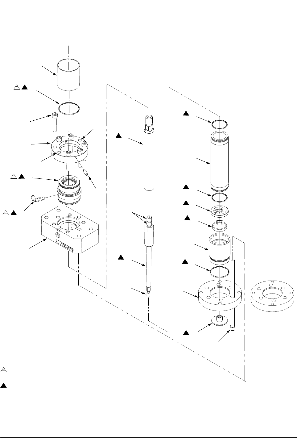
The following paragraphs provide procedures for
repairing the stainless steel hydraulic section.
Disassemble the Hydraulic Section
1. See Figure 8. Remove the solvent chamber (1) and
the O-ring (2) from the packing gland (5). Discard
the O-ring.
2. Remove the packing gland assembly:
a. Remove the screws (3) from the collar (4). Insert
two screws into the threaded holes (9) as shown.
b. Alternate tightening the screws to remove the
packing gland assembly from the upper
pump body (8).
c. Loosen the set screws (6) and remove the
packing gland (5) from the collar (4).
d. Remove the fittings (7) from the packing gland.
3. Remove the shovel adapter (20) from the shovel
rod (12).
4. Remove the screws (21) securing the cylinder
assembly and follower plate housing (19) to the upper
pump body (8). Remove the follower plate housing.
5. Remove the bottom housing (17), O-ring (18), lower
check plate (16), and spacer (15). Discard
the O-ring.
6. Remove the cylinder housing (13) from the upper
pump body (8). Remove and discard the O-rings (14)
from the cylinder housing.
7. Remove the shovel rod (12) from the plunger
rod (11).
8. Clean the parts with a compatible solvent. Refer to
Table 4 in the Specifications section for wetted
component materials.
9. Inspect parts for nicks, scratches, wear, and damage.
Replace parts if necessary.
Assemble the Hydraulic Section
1. See Figure 8. Apply threadlock adhesive (10) to the
threads of the fittings (7). Install the fittings into the
packing gland (5) and tighten securely.
2. Apply Mobil SHC 634 lubricant (22) to the packing
gland O-ring (2) and the I.D. of the packing gland (5).
3.
Install the upper collar (4) onto the packing gland (5).
Tighten the set screws (6) until they make contact with
the packing gland. Do not over tighten the set screws.
4. Install the packing gland assembly onto the body (8).
5. Apply Never Seeze (23) to the threads of the
screws (3). Install the screws into the packing gland
assembly and tighten to 102−108 Nm (75−80 ft-lb).
6. Apply Mobil SHC 634 lubricant (22) to the cylinder
housing O-rings (14). Install the O-rings onto the
cylinder housing (13). Install the cylinder housing
onto the upper pump body (8).
7. Assemble the plunger rod assembly:
a. Apply Never Seez (23) to the upper threads and
pilot of the shovel rod (12).
b. Connect the shovel rod to the plunger rod (11)
and tighten to 272−298 Nm (200−220 ft-lb).
c. Apply a thin coat of Mobil SHC 634 lubricant (22)
to the plunger rod (11) and the shovel rod (12).
8. Using either an arbor press or hydraulic press, install
the plunger rod assembly into the cylinder housing
(13) and packing gland (5).
9. Install the spacer (15) and lower check plate (16)
onto the rod assembly.
10. Install the bottom housing (17) onto the cylinder
housing (13). Apply Mobil SHC 634 lubricant (22) to
the O-ring (18) and install it onto the bottom housing.
11. Install the follower plate housing (19) onto the bottom
housing (17).
12. Apply Never Seez (23) to the threads of the
screws (21). Perform the following:
a. Install the screws through the follower plate
housing (19) and into the upper pump body (8).
b. Hand-tighten two opposing screws at the same
time until the follower plate housing, bottom
housing (17), and cylinder housing (13) are
secured to the upper pump body (8).
Hand-tighten the remaining screws as shown.
c. After performing step 12b, simultaneously tighten
each screw 1/8 turn at a time in the sequence
shown to 102−108 Nm (75−80 ft-lb).
13. Apply Never Seez (23) to the lower threads of the rod
assembly. Install the shovel adapter (20) to the rod
assembly and tighten to 75−81 Nm (55−60 ft-lb).
14. Install the solvent chamber cup (1) onto the
packing gland assembly.
Rhino SD2/XD2 Pumps
15
Part 1073520-12
E 2013 Nordson Corporation
1
2
3
4
8
11
12
23
13
14
15
16
17
18
19
20
21
22
22
22
5
7
6
22
22
23
23
14
22
PARTS ARE INCLUDED IN THIS KIT:
XD2 8.1 CUBIC INCH STAINLESS STEEL PACKING GLAND SERVICE KIT 1074331
PARTS ARE INCLUDED IN THIS KIT:
XD2 8.1 CUBIC INCH ARW STAINLESS STEEL DRIVE TRAIN SERVICE KIT 1074332
SEQUENCE
2
3
4
1
TORQUE
5
6
10
23
9
9
23
Figure 8 Stainless Steel Hydraulic Section Repairs

Rhino SD2/XD2 Pumps
16
E 2013 Nordson Corporation
Part 1073520-12
Air Motor
The following paragraphs provide repair procedures for
the air motor section.
Replace the Trip-Rod U-Cup
The trip-rod U-cup can be replaced without removing the
air motor from the pump.
Remove the Trip-Rod U-Cup
1. See Figure 9. Remove the screws (2) securing the
cover (1) to the trip-rod assembly (6).
2. Remove the screws (5) and washers (4)
securing the trip-lever mounting pad (15) to
the trip-rod assembly (6).
3. Swing the trip-lever mounting pad (15) away from the
seal retainer plate (11).
4. Place a wrench on the flats of the piston rod (13).
Remove the nut (7) securing the trip-bar (8) to the
piston rod.
5. Remove the screws (9) and washers (10) securing
the seal retainer plate (11) to the trip-rod
retainer (12).
! CAUTION !
Use a small screwdriver or an O-ring pick in
the next step to prevent damage to the U-cup
bore and piston rod.
6. Remove the U-cup (14) from the trip-rod
retainer (12). Discard the U-cup.
Install the Trip-Rod U-Cup
1. See Figure 9. Lubricate the new U-cup (14) with
TFE grease (16). Insert the U-cup into the trip-rod
retainer (12) as shown.
2. Install the seal retainer plate (11) onto the trip-rod
retainer (12) using the screws (9) and washers (10).
Tighten the screws to 22−25 ft-lb (30−33 Nm).
3. Place a wrench on the flats of the piston rod (13).
Install the trip-bar (8) to the piston rod using the
nut (7). Tighten the nut securely.
4. Perform the following:
a. Make sure that the mounting pad pins (3)
protrude through the trip-rod assembly (6)
as shown.
b. Secure the trip-lever mounting pad (15) to
the trip-rod assembly using the screws (5)
and washers (4). Tighten the screws
to 22−25 ft-lb (30−33 Nm).
5. Install the cover (1) to the trip-rod assembly using the
screws (2). Tighten the screws securely.