Nordson_EFD_Rhino_SD2_XD2_Operating Manual.pdf - 第23页
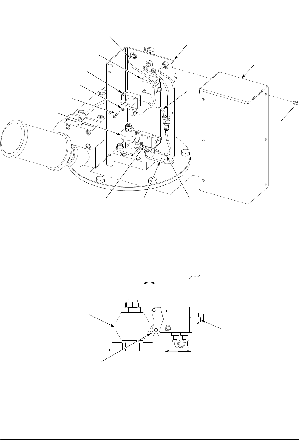
Rhino SD2/XD2 Pumps 19 Part 1073520-12 E 2013 Nordson Corporation 0.040 − 0.070 IN. IN OUT ADJUSTMENT SET SCREW PILOT V AL VE ROLLER LEVER (1.02 − 1.78 MM) BOTTOMED OUT TRIP BAR 2 1 5 4 9 10 11 8 3 7 6 12 13 LOWER PILOT …

Rhino SD2/XD2 Pumps
18
E 2013 Nordson Corporation
Part 1073520-12
Replace a Pilot Valve
The pilot valves can be replaced without removing the air
motor from the pump.
Remove and Install a New Pilot Valve
1. See Figure 10. Remove the screws (1) securing the
cover (2) to the trip-rod assembly (3).
2. Disconnect the tubing (4, 5 or 6, 7) from the pilot
valve (9 or 13).
3. Remove the screw (11) and washer (10) securing the
pilot valve (9 or 13) to the mounting pad (8).
4. Install the pilot valve (9 or 13) to the mounting
pad (8) using the washer (10) and screw (11).
Thread the screw into the mounting pad. Do not
tighten the screw at this time.
Adjust the New Pilot Valve
1. Cycle the air motor:
a. Upper Pilot Valve—Cycle the air motor until the
trip-bar (12) is fully extended.
b. Lower Pilot Valve—Cycle the air motor until the
trip-bar (12) is fully retracted.
2. Set the gap between the roller lever on the pilot
valve (9 or 13) and the trip-bar (12):
a. Make sure that pilot valve moves freely and that
the roller lever is bottomed out.
b. Using the adjustment set screw, move the
pilot valve in or out to obtain a gap of
0.040−0.070 in. (1.02−1.78 mm) between the
roller lever on the pilot valve and the trip-bar.
Tighten the hold-down screw securely.
3. Connect the tubing (4, 5 or 6, 7) to the pilot
valve (9 or 13). See Figure 25 in the Specifications
section for the proper tube routings.
4. Install the cover (1) to the trip-rod assembly using the
screws (2). Tighten the screws securely.
Rhino SD2/XD2 Pumps
19
Part 1073520-12
E 2013 Nordson Corporation
0.040−0.070 IN.
IN OUT
ADJUSTMENT
SET SCREW
PILOT VALVE
ROLLER LEVER
(1.02−1.78 MM)
BOTTOMED OUT
TRIP BAR
2
1
5
4
9
10
11
8
3
7
6
12
13
LOWER PILOT VALVE SHOWN
Figure 10 Replacing a Pilot Valve

Rhino SD2/XD2 Pumps
20
E 2013 Nordson Corporation
Part 1073520-12
Replace the Supply
Tube Quad- and O-Rings
Use the following procedure to replace the supply tube
quad- and O-rings.
Remove the Supply Tube Quad- and O-Rings
1. See Figure 11. Remove the screws (4) and
washers (5) securing the upper supply tube
retainer (3) to the air manifold (1).
2. Remove the screws (11) and washers (10) securing
the lower supply tube retainer (9) to the base
plate (18).
3. Remove the supply tube (6) from the air manifold (1)
and base plate (18).
4. Remove the upper and lower retainers (3, 9) from the
supply tube and clean them in a compatible solvent if
necessary.
5. Remove the O-ring (2) from the air manifold (1).
Remove the Quad-rings (7) and O-ring (8) from the
base plate (18). Discard the Quad- and O-rings.
Install the Supply Tube Quad- and O-Rings
1. See Figure 11. Lubricate the Quad-rings (7) and
O-rings (8) with TFE grease. Install the Quad-rings
and O-ring into the base plate (18) as shown.
2. Install the lower retainer to the base plate (18) using
the washers (10) and screws (11). Only finger
tighten the screws at this time.
3. Lubricate the air manifold O-ring (2) with TFE grease
and install it into the air manifold (1).
4. Install the upper retainer (3) onto the air supply
tube (6).
5. Carefully insert the bottom portion of the air supply
tube (6) through the lower retainer (9) and into the
base plate (18).
6. Carefully insert the upper portion of the air supply
tube (6) into the air manifold (1).
7. Secure the upper retainer (3) to the air manifold (1)
using the screws (4) and washers (5). Tighten the
screws to 10−12 ft-lb (13−16 Nm).
8. Tighten the lower retainer screws (11)
to 10−12 ft-lb (13−16 Nm).
Replace the Piston Rod
Retainer U-Cup and O-Ring
1. See Figure 11. Remove the screws (13) and
washers (14) securing the piston rod retainer (15) to
the base plate (17).
2. Remove the O-ring (16) and U-cup (12) from
the piston rod retainer (15). Discard the O-ring
and U-cup.
3. Lubricate the new O-ring (16) and U-cup (12) with
TFE grease. Insert the O-ring and U-cup into the
piston rod retainer (15) as shown.
4. Install the piston rod retainer (15) onto the base
plate (17) using the screws (13) and washers (14).
Tighten the screws to 22−25 ft-lb (30−33 Nm).