Nordson_EFD_Rhino_SD2_XD2_Operating Manual.pdf - 第26页
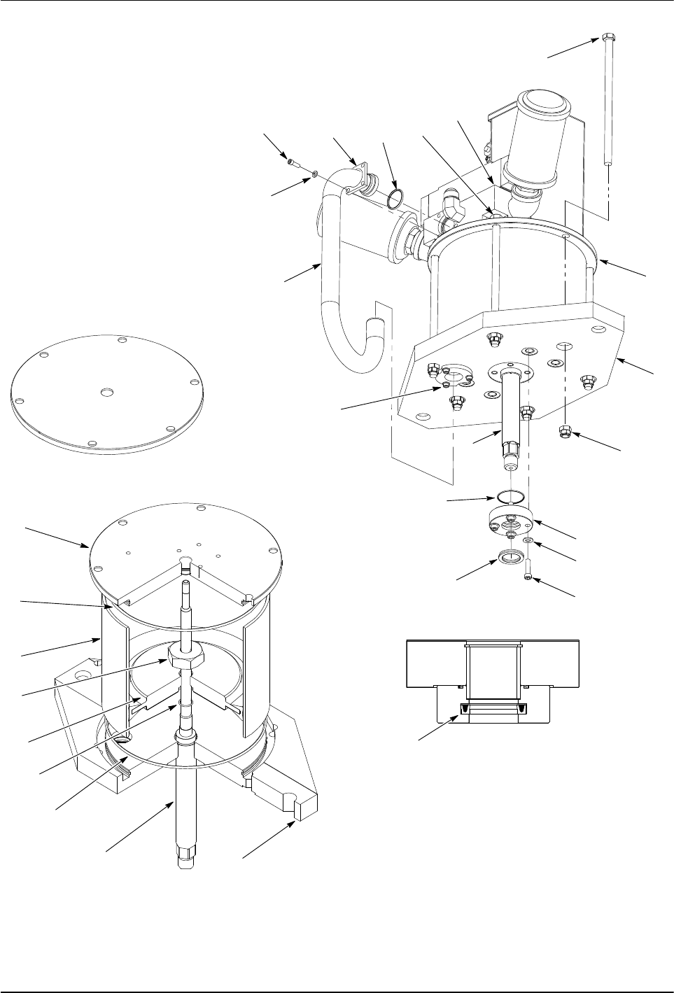
Rhino SD2/XD2 Pumps 22 E 2013 Nordson Corporation Part 1073520-12 Replace the Piston Assembly Use the following procedure to replace the piston assembly . Remove the Piston Assembly 1. See Figure 12. Remove the screws (1…
Rhino SD2/XD2 Pumps
21
Part 1073520-12
E 2013 Nordson Corporation
U-CUP
ORIENTATION
2
3
4
5
6
7
8
12
9
10
11
13
14
15
16
17
18
1
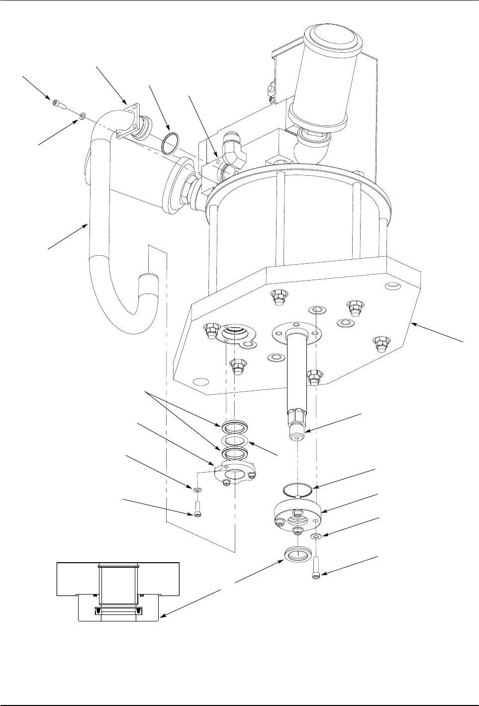
Figure 11 Replacing the Base Plate Seals and Rings
Rhino SD2/XD2 Pumps
22
E 2013 Nordson Corporation
Part 1073520-12
Replace the Piston Assembly
Use the following procedure to replace the
piston assembly.
Remove the Piston Assembly
1. See Figure 12. Remove the screws (1) securing the
trip-rod assembly cover (2).
2. Place a wrench on the flats of the piston rod (5).
3. Remove the nut (3) securing the trip-bar (4) to the
piston rod (5).
4. See Figure 13. Remove the screws (6) and
washers (7) securing the upper supply tube
retainer (5) to the air manifold (2).
5. Loosen the lower supply tube retainer screws (9).
6. Remove the supply tube (8) from the air manifold (2)
and base plate (17). Remove and discard the
O-ring (4) from the air manifold (2).
7. Remove the screws (13) and washers (14) securing
the piston rod retainer (15) to the base plate (17).
Remove the O-ring (11) and U-cup (12). Discard the
O-ring and U-cup.
8. Remove the screws (1) and nuts (16) securing the air
motor cap (18) to the base plate (17). Use a wrench
on the flats of the two screws (3) below the air
manifold (2) to remove the nuts.
9. Remove the air motor cap (18) and set it on a flat
surface. Remove and discard the air motor cap
O-ring (19).
10. Remove the air cylinder (20) and O-ring (19) from the
base plate (17). Discard the O-ring. Remove the
piston assembly from air cylinder.
11. Remove the nut (21) securing the piston (22) to the
piston rod (10). Remove the O-ring (23) from the
piston rod and discard.
3
4
5
2
1
Figure 12 Removing the Trip-Rod Cover
Install the Piston Assembly
1. See Figure 13. Apply TFE grease to the
following parts:
S inner surface of the air cylinder (20)
S piston (22)
S O-rings (4, 11, 19, 23)
S U-cup (12)
2. Install the O-ring (23) onto the piston rod (10).
3. Apply Loctite 242 (24) to the upper threads of the
piston rod (10). Install the piston (22) onto the piston
rod. Install the nut onto the piston rod and tighten to
200−220 ft-lb (271−298 Nm).
4. Assemble the piston assembly and air cylinder (20):
a. Insert the piston assembly into the air cylinder at
a 20−30 degree angle to ensure that there is an
equal amount of grease on each side of the
piston. When the piston reaches the middle of
the air cylinder, rotate it to the proper position.
b. Apply TFE grease to the piston rod (10).
5. Install the O-rings (19) onto the base plate (17) and
air motor cap (18).
6. Install the air cylinder/piston assembly onto the base
plate (17).
7. Install the air motor cap (18) onto the air cylinder (20)
using the screws (1, 3). Perform the following:
a. Install the nuts (16) onto the screws.
b. Hand-tighten two opposing screws at the
same time until the air motor cap is secured to
the base plate.
c. After performing step 7b, secure the air motor
cap to the base plate by tightening the screws in
the sequence shown to 30−35 Nm (41−47 ft-lb).
8. Insert the O-ring (11) and U-cup (12) into the piston
rod retainer (15) as shown.
9. Install the piston rod retainer (15) onto the
base plate (17) using the screws (13) and
washers (14). Tighten the screws to
22−25 ft-lb (30−33 Nm).
10. Carefully insert the bottom portion of the air supply
tube (8) through the lower retainer (9) and into the
base plate (17).
11. Carefully insert the upper portion of the air supply
tube (8) into the air manifold (2).
12. Secure the upper retainer (5) to the air manifold (2)
using the screws (6) and washers (7). Tighten the
screws to 10−12 ft-lb (13−16 Nm).
13. Tighten the screws on the lower retainer (9)
to 10−12 ft-lb (13−16 Nm).
14. See figure 12. Install the trip-bar (4) to the piston
rod (5) using the nut (3). Tighten the nut securely.
15. Install the cover (2) to the air motor using the
screws (1). Tighten the screws securely.
Rhino SD2/XD2 Pumps
23
Part 1073520-12
E 2013 Nordson Corporation
3
2
16
17
10
11
12
15
14
13
9
8
4
5
7
6
1
18
19
21
23
10
19
22
17
18
20
12
24
U-CUP
ORIENTATION
1
2
3
4
5
6
TORQUE
SEQUENCE
Figure 13 Replacing the Piston