Nordson_EFD_Rhino_SD2_XD2_Operating Manual.pdf - 第7页
Rhino SD2/XD2 Pumps 3 Part 1073520-12 E 2013 Nordson Corporation Description See Figure 1 and refer to T able 1 for a description of the pump components. NOTE: Installation and operation are dependent upon the bulk unloa…
Rhino SD2/XD2 Pumps
2
E 2013 Nordson Corporation
Part 1073520-12
WARNING: Any injury caused by high pressure
liquid can be serious. If you are injured or even
suspect an injury:
S Go to an emergency room immediately.
S Tell the doctor that you suspect an injection injury.
S Show him this card
S Tell him what kind of material you were spraying
MEDICAL ALERT—AIRLESS SPRAY WOUNDS: NOTE
TO PHYSICIAN
Injection in the skin is a serious traumatic injury. It is
important to treat the injury surgically as soon as
possible. Do not delay treatment to research toxicity.
Toxicity is a concern with some exotic coatings injected
directly into the bloodstream.
Consultation with a plastic surgeon or a reconstructive
hand surgeon may be advisable.
The seriousness of the wound depends on where the
injury is on the body, whether the substance hit
something on its way in and deflected causing more
damage, and many other variables including skin
microflora residing in the paint or gun which are blasted
into the wound. If the injected paint contains acrylic latex
and titanium dioxide that damage the tissue’s resistance
to infection, bacterial growth will flourish. The treatment
that doctors recommend for an injection injury to the
hand includes immediate decompression of the closed
vascular compartments of the hand to release the
underlying tissue distended by the injected paint,
judicious wound debridement, and immediate antibiotic
treatment.
Fire Safety
To avoid a fire or explosion, follow these instructions.
S Ground all conductive equipment. Use only
grounded air and fluid hoses. Check equipment and
workpiece grounding devices regularly. Resistance
to ground must not exceed one megohm.
S Shut down all equipment immediately if you notice
static sparking or arcing. Do not restart the
equipment until the cause has been identified and
corrected.
S Do not smoke, weld, grind, or use open flames
where flammable materials are being used or stored.
S Do not heat materials to temperatures above those
recommended by the manufacturer. Make sure heat
monitoring and limiting devices are working properly.
S Provide adequate ventilation to prevent dangerous
concentrations of volatile particles or vapors. Refer
to local codes or your material MSDS for guidance.
S Do not disconnect live electrical circuits when
working with flammable materials. Shut off power at
a disconnect switch first to prevent sparking.
S Know where emergency stop buttons, shutoff valves,
and fire extinguishers are located. If a fire starts in a
spray booth, immediately shut off the spray system
and exhaust fans.
S Shut off electrostatic power and ground the charging
system before adjusting, cleaning, or repairing
electrostatic equipment.
S Clean, maintain, test, and repair equipment
according to the instructions in your equipment
documentation.
S Use only replacement parts that are designed for use
with original equipment. Contact your Nordson
representative for parts information and advice.
Halogenated Hydrocarbon
Solvent Hazards
Do not use halogenated hydrocarbon solvents in a
pressurized system that contains aluminum components.
Under pressure, these solvents can react with aluminum
and explode, causing injury, death, or property damage.
Halogenated hydrocarbon solvents contain one or more
of the following elements:
Element Symbol Prefix
Fluorine F “Fluoro-”
Chlorine Cl “Chloro-”
Bromine Br “Bromo-”
Iodine I “Iodo-”
Check your material MSDS or contact your material
supplier for more information. If you must use
halogenated hydrocarbon solvents, contact your Nordson
representative for information about compatible Nordson
components.
Action in the Event of a
Malfunction
If a system or any equipment in a system malfunctions,
shut off the system immediately and perform the
following steps:
S Disconnect and lock out system electrical power.
Close hydraulic and pneumatic shutoff valves and
relieve pressures.
S Identify the reason for the malfunction and correct it
before restarting the system.
Disposal
Dispose of equipment and materials used in operation
and servicing according to local codes.
Rhino SD2/XD2 Pumps
3
Part 1073520-12
E 2013 Nordson Corporation
Description
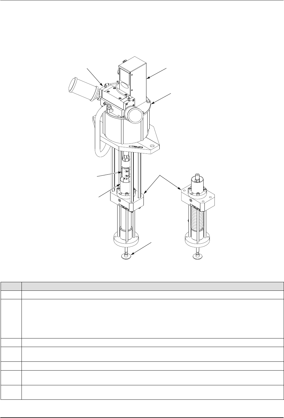
See Figure 1 and refer to Table 1 for a description of the
pump components.
NOTE: Installation and operation are dependent upon
the bulk unloader and application. Refer to your system
documentation for detailed information.
5
1
4
3
2
6
7
TEMPERATURE CONDITIONED
HYDRAULIC SECTION
Figure 1 Typical Rhino SD2/XD2 Pump
Table 1 Rhino Pump Components
Item Description
1 10-Inch Air Motor: Drives the hydraulic section.
2 Hydraulic Section: The hydraulic section pressurizes the material and forces it out of the pump. The
following hydraulic section are available:
S Standard 5.8- and 8.1- cubic inch
S 5.8- and 8.1- cubic inch temperature conditioned
S Stainless Steel 8.1-cubic inch
3 Shovel: Forces material into the hydraulic section.
4 Solvent Chamber: Contains fluid to lubricate the plunger and packing gland seals; prevents material from
hardening on the plunger rod
5 Coupling: Connects the air motor coupling shaft to the hydraulic section plunger rod.
6 Main Air Control Valve: Controls the air motor shaft movement by shifting a spool. The spool exhausts air
on one side of the piston and directs air pressure to the opposite side of the piston.
7 Pilot and Intermediate Valves: Controls the direction of the air motor shaft. Has manual overrides to
manually override the upward and downward stroke of the pump.
Rhino SD2/XD2 Pumps
4
E 2013 Nordson Corporation
Part 1073520-12
Theory of Operation
The following paragraphs provide theory of operation for
a typical pump air motor and hydraulic section.
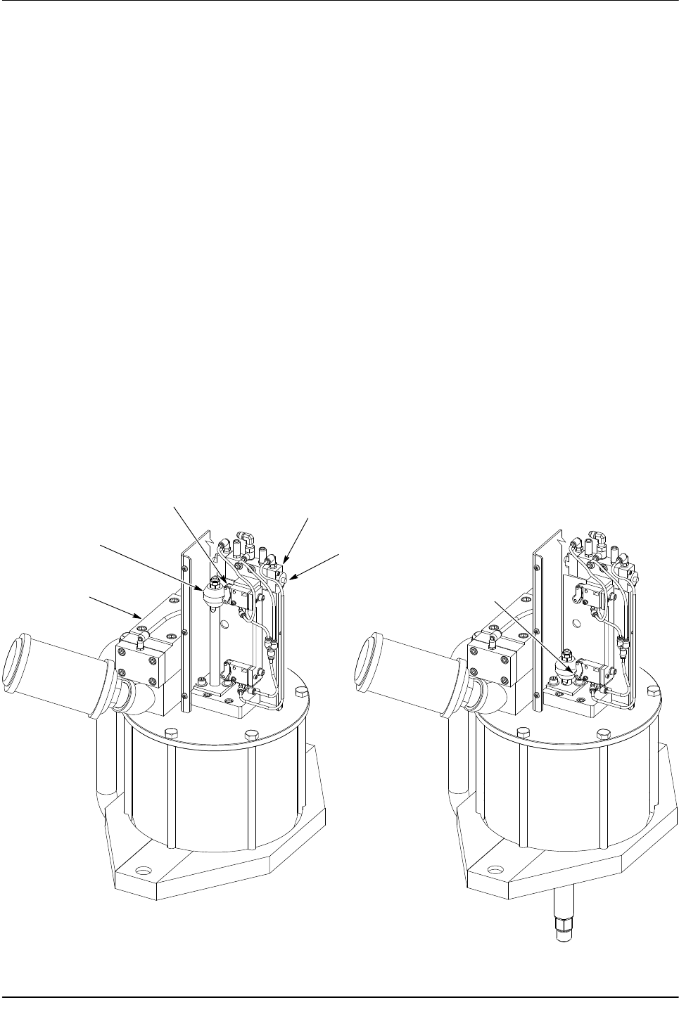
Air Motor
See Figure 2. The air motor drives the hydraulic section.
A five-way two-position main air control valve controls
the direction of the air motor shaft movement.
When the air motor piston moves up and down, the
piston trip-bar trips the pilot valves. The pilot valves
send momentary signals to an intermediate valve. The
intermediate valve sends a positive continuous signal to
the main air motor control valve for each direction of
travel. The intermediate valve has manual overrides for
air motor directional changes for performing repairs and
assembling.
Hydraulic Section
See Figure 3. The hydraulic section has a shovel
attached to the end of the hydraulic plunger that projects
into the center of the follower plate. The shovel moves
up and down with the plunger, helping to force material
into the hydraulic section. The hydraulic section
pressurizes the material and forces it out of the pump.
When the plunger strokes downward, the piston/upper
check opens and the lower check closes. Material
between the upper and lower checks is forced upward
through the piston. The material above the upper check
pressurizes and flows out of the material output port.
NOTE: The stainless steel version is a single-acting
hydraulic section that only displaces material on the
downward stroke.
During the upward pump stroke, the plunger and shovel
are pulled upward and the piston/upper check closes.
The lower check opens and allows material to pass into
the lower pump chamber below the upper check. As the
plunger and piston move upward, material from the upper
pump chamber is forced out of the material outlet port.
The solvent chamber surrounds the plunger. The
chamber contains solvent chamber fluid that lubricates
the plunger and packing gland seals. This fluid keeps
material from hardening on the plunger and minimizes
wear on the packing gland seals. The bleed valve is
used to bleed air from the pump.
DOWN STROKE
PILOT VALVE
MAIN AIR MOTOR
CONTROL VALVE
AIR MOTOR
PISTON TRIP-BAR
UP STROKE
PILOT VALVE
UP
STROKE
INTERMEDIATE
VALVE
MANUAL
OVERRIDE
DOWN
STROKE
Figure 2 Air Motor