Maintenance Manual.pdf - 第130页
RL131 MAINTENANCE MANUAL 7.2 Periodic Insp ection Ite ms DA8MEC-Z0-020-A 0 7.2-1 7.2. Periodic Inspection Items DA8MEC-Z0-020-A0 7.2.1 Daily Check Items The following tabl es summari ze the periodic i nspectio n item s t…
RL131
MAINTENANCE MANUAL
7.1 Introduction
DA8MEC-Z0-010-A0
7.1-2
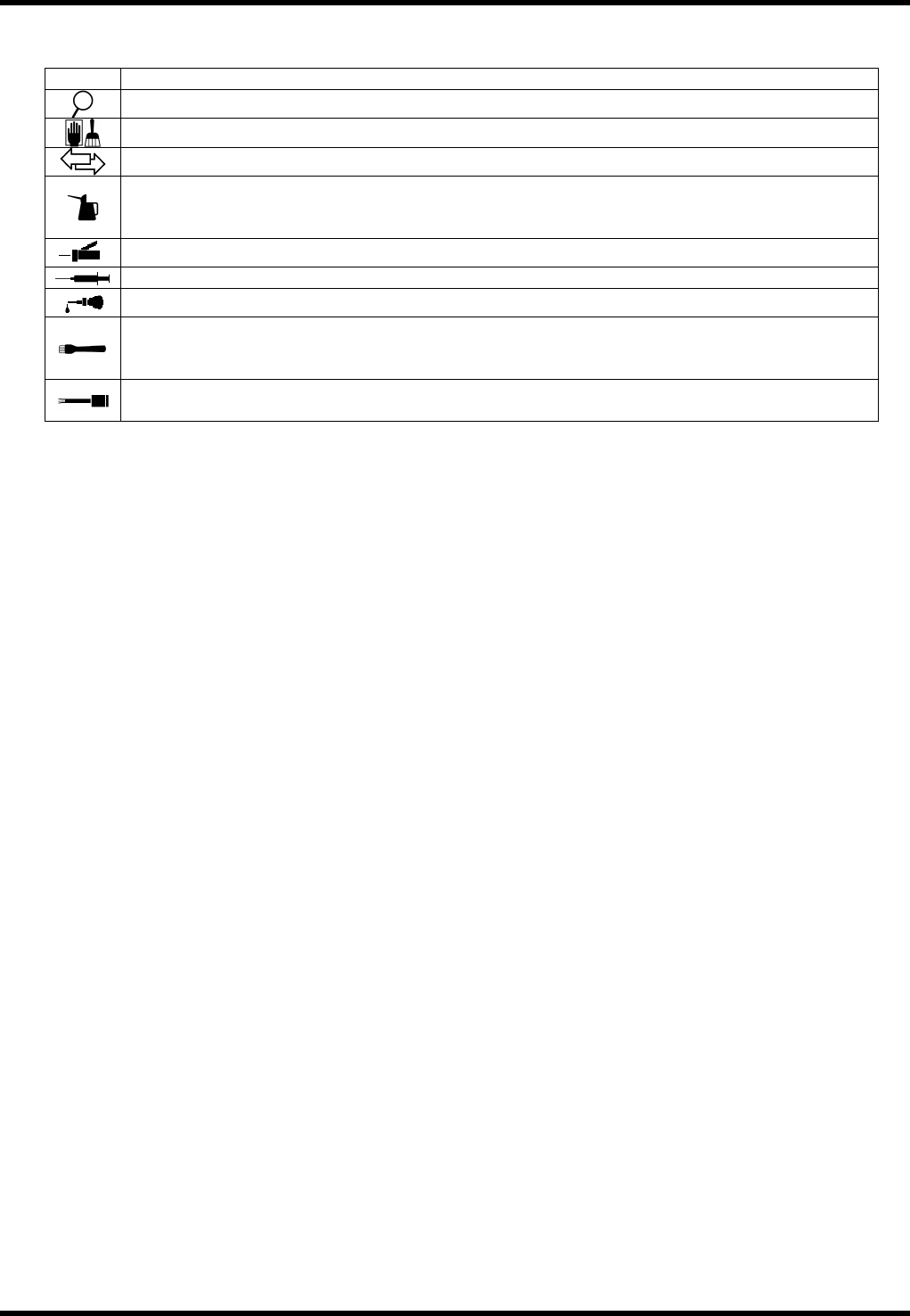
7.1.2 Symbols in the Drawings
The following icons are used to describe the tasks for easy readability.
Icon Task
Indicates check for proper machine operation/adjustments.
Indicates cleaning.
Indicates parts replacement.
Indicates lubricant replacement.
Drain the used oil from the drain port and inject adequate amount of new lubricant from the
injection port.
Indicates lubrication with a grease gun unit.
Indicates lubrication with a syringe.
Indicates lubrication of machine oil with an oiler.
Indicates grease application with a brush.
Remove dust or old oil adhered to the surface of the part completely and apply a thin coat of
grease.
Remove dust or old oil adhered to the surface of the part completely and apply a thin coat of
grease.
Oiling Period
The period of oiling is set as a premise in the following.
One day: for 20 hours, one week: for six days, and one month: for 25 days
Recommended Lubricants
== Refer to ‘Mtn. / PREPARED MATERIALS / Recommended Lubricants’.
=REMARKS=
Use oil equivalent to ISO VG32 for the machine oil to be supplied to the lubricator.
RL131
MAINTENANCE MANUAL
7.2 Periodic Inspection Items
DA8MEC-Z0-020-A0
7.2-1
7.2. Periodic Inspection Items
DA8MEC-Z0-020-A0
7.2.1 Daily Check Items
The following tables summarize the periodic inspection items that are to be performed daily.
For the details of inspection positions and lubrication method, refer to the subsequent sections.
Numbers in the Unit column show the relevant sections to be referred to.
Inspection (Daily)
Unit No.
Item Task Description
Remove oil or dust.
Make sure that the belt is not worn or damaged.
a.
Belt
Make sure that belt tension is properly adjusted.
Make sure that width of the rail is 0.5 - 1 mm wider
than the PCB to be used.
Make sure that the rail moves up/down properly.
7.3.3
Loader/Unloader
b.
Rail
Make sure that PCB transfer is smooth.
Make sure that the lever moves up/down smoothly.
Make sure that the lever slides smoothly.
Lever
Make sure that the lever moves lightly at the
support.
7.3.5
PCB Transfer
Unit
b.
Transfer pin
Make sure that the transfer pin is inserted into the
PCB hole correctly.
a.
Insertion chuck
Make sure that insertion chunk opens/closes
smoothly.
b.
Insertion pusher rubber
Make sure that the insertion pusher rubber is not
worn or damaged.
c.
Insertion pusher
Make sure that the insertion pusher smoothly slides
vertically.
7.4.1
Insertion Head
d.
Sensor
Wipe off any dust or dirt at the edge of the sensor.
7.4.2
Insertion Drive
Unit
a.
Worm reduction gear
Make sure that oil is not leaking from the reduction
gear.
7.4.4
Transfer Chuck
a.
Transfer chuck
Make sure that the transfer chuck opens/closes
smoothly.
a.
Backup pin
Make sure that the backup pin moves up/down
smoothly.
7.6.1
Part Positioning
Unit
b.
Lever support
Make sure that the lever is not worn or damaged.
Clean the edge of the lead guide with a brush and
remove any cut wastes.
7.6.2
Lead Correction
Unit
a.
Lead guide
Make sure that lubricant or dust is not adhering to
the lead cutter.
Clean the edge of the lead cutter with a brush and
remove any cut waste.
Make sure that lubricant or dust is not adhering to
the lead cutter.
a.
Lead cutter
Make sure that the lead cutter is not worn or
damaged.
b.
Lead cutter lever
Make sure that the lead cuter lever opens/closes
smoothly.
7.6.3
V-cut Unit
c.
Sensor
Wipe off any dust or dirt at the edge of the sensor.
7.6.4
Part Processing
Drive Unit
a.
Worm reduction gear
Make sure that lubricant is not leaking out from the
worm reduction gear.
RL131
MAINTENANCE MANUAL
7.2 Periodic Inspection Items
DA8MEC-Z0-020-A0
7.2-2
Unit No.
Item Task Description
Clean the edge of the movable/fixed blades with a
brush and remove any cut waste.
a.
Movable/fixed blade
Make sure that the movable/fixed blade is not worn
or damaged.
b.
Cord Make sure that the cord is not damaged.
7.7.1
Upper Anvil
c.
Backup pin
Make sure that the backup pin is not worn or
damaged.
7.7.2
Anvil Drive Unit
a.
Worm reduction gear
Make sure that lubricant is not leaking out from the
worm reduction gear.
a.
Main pressure Make sure that air pressure is at 0.5 MPa.
7.8.3
Main Regulator
b.
Pneumatic circuit
Make sure that there is no air leakage.
Oiling (Daily)
Unit No.
Item Task
Oiling
volume
Description
7.7.1
Upper Anvil
1.
Pin pivot
1 to 2
drops
Apply 1 or 2 drops of the machine oil
to the oil port.