Maintenance Manual.pdf - 第133页
RL131 MAINTENANCE MANUAL 7.2 Periodic Ins pection Ite ms DA8MEC-Z0-020-A 0 7.2-4 Unit No. Item Task Oiling volume Description 1. LM guide 2. Cam follower 3. Open/close p in 4. Hook 0.5 cm 3 Remove all dirt a dhering on t…
RL131
MAINTENANCE MANUAL
7.2 Periodic Inspection Items
DA8MEC-Z0-020-A0
7.2-3
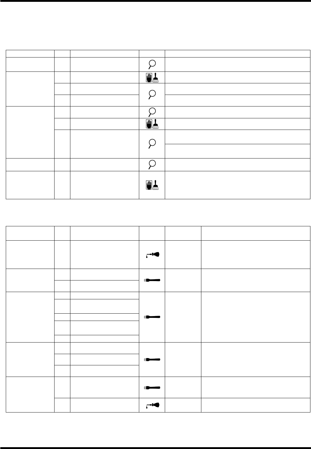
7.2.2 Weekly Check Items
The following tables summarize the periodic inspection items that are to be performed weekly.
For the details of inspection positions and lubrication method, refer to the subsequent sections.
Numbers in the Unit column show the relevant sections to be referred to.
Inspection (Weekly)
Unit No.
Item Task Description
7.3.2
Positioner
a.
Reference pin
Make sure that the reference pin is not worn or
damaged.
c.
Sensor
Remove oil or dust.
d.
Belt Make sure that belts do not slip.
7.3.3
Loader/Unloader
e.
Belt roller
Make sure that all rollers turn.
c.
Belt
Make sure that the belt is not worn.
d.
Shaft
Sliding surface: Remove dirt or dust.
Make sure that the transfer pin claw is not
loosened.
7.3.5
PCB Transfer
Unit
e.
Transfer pin
Make sure that the transfer pin claw is not
damaged or deformed.
7.4.6
Main Drive Unit
a.
Manual rotation wheel
Make sure that the gear rotates smoothly.
7.8.1
Cut Waste Bottle
and Tape Waste
Receptacle
a.
Filter
Clean the filter using air blow.
(Replace it if damaged.)
Oiling (Weekly)
Unit No.
Item Task
Oiling
volume
Description
7.4.1
Insertion Head
1.
Insertion chuck support
shaft
1 drop to
each bush
Apply oil to the support shaft. (Apply
oil as needed if the unit does not
open/lose smoothly after daily
inspection.)
1.
Cam
7.4.2
Insertion Drive
Unit
2.
Cam follower
0.5 cm
3
Remove all dirt adhering on the
surface completely and apply a thin
coat of grease.
1.
Cam follower
2.
Opening/closing
claw
3.
Plate
4.
Opening/closing
cam
7.4.4
Transfer chuck
unit
5.
Grease nipple
0.5 cm
3
Remove all dirt adhering on the
surface completely and apply a thin
coat of grease.
1.
Holder A
2.
Holder B
7.4.5
Transfer Head
3.
Outer shaft
0.5 cm
3
Remove all dirt adhering on the
surface completely and apply a thin
coat of grease.
1.
LM guide
0.5 cm
3
Remove all dirt adhering on the
surface completely and apply a thin
coat of grease.
7.6.1
Part Positioning
Unit
2.
Lever support
1 to 2
drops
Apply 1 or 2 drops to the support.
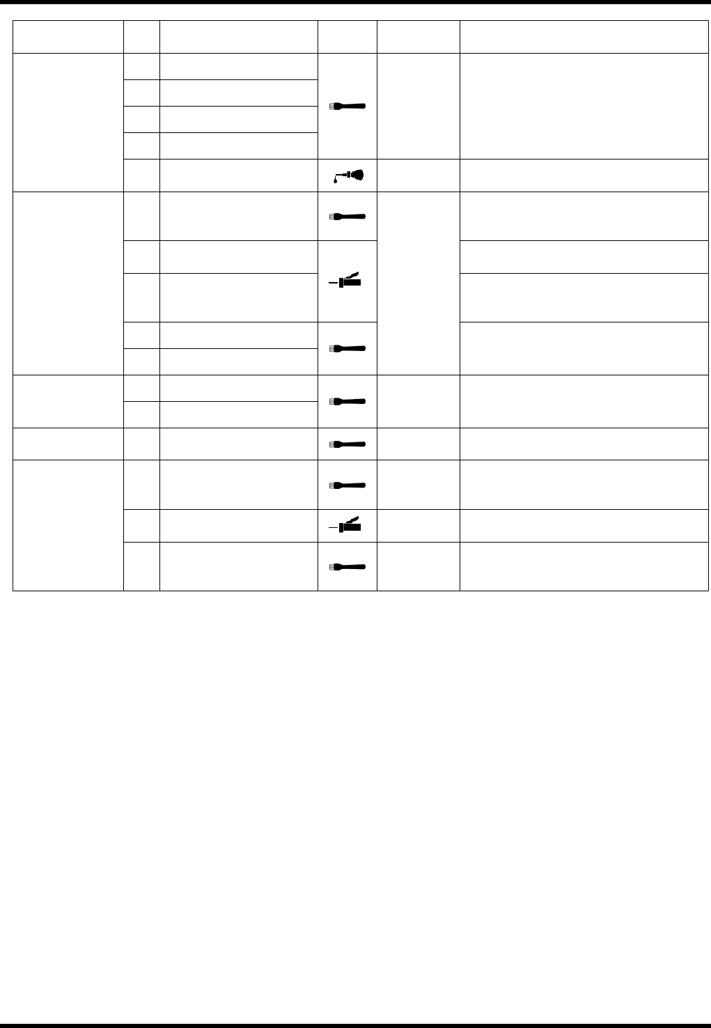
RL131
MAINTENANCE MANUAL
7.2 Periodic Inspection Items
DA8MEC-Z0-020-A0
7.2-4
Unit No.
Item Task
Oiling
volume
Description
1.
LM guide
2.
Cam follower
3.
Open/close pin
4.
Hook
0.5 cm
3
Remove all dirt adhering on the
surface completely and apply a thin
coat of grease.
7.6.2
Lead Correction
Unit
5.
Oil port
1 to 2
drops
Apply 1 or 2 drops of the machine oil
to the oil port.
1.
LM guide
Remove all dirt adhering on the
surface completely and apply a thin
coat of grease.
2.
Grease nipple
Apply 1 shot of grease with a grease
gun.
3.
Grease nipple
Apply 1 shot of grease with a grease
gun.
(Nipple type NL)
4.
Pusher cam
7.6.3
V-cut Unit
5.
Hook
0.5 cm
3
Remove all dirt adhering on the
surface completely and apply a thin
coat of grease.
1.
Cam
7.6.4
Part Processing
Drive Unit
2.
Cam follower
0.5 cm
3
Remove all dirt adhering on the
surface completely and apply a thin
coat of grease.
7.7.1
Upper Anvil
2.
Lever sliding surface
0.1 cm
3
Apply oil to the periphery and inside
of the roller.
1.
Cam
0.5 cm
3
Remove all dirt adhering on the
surface completely and apply a thin
coat of grease.
2.
Cam follower
1 shot
Inject 1 shot of grease using a grease
gun.
7.7.2
Anvil Drive Unit
3.
Cam follower
0.5 cm
3
Remove all dirt adhering on the
surface completely and apply a thin
coat of grease.
RL131
MAINTENANCE MANUAL
7.2 Periodic Inspection Items
DA8MEC-Z0-020-A0
7.2-5
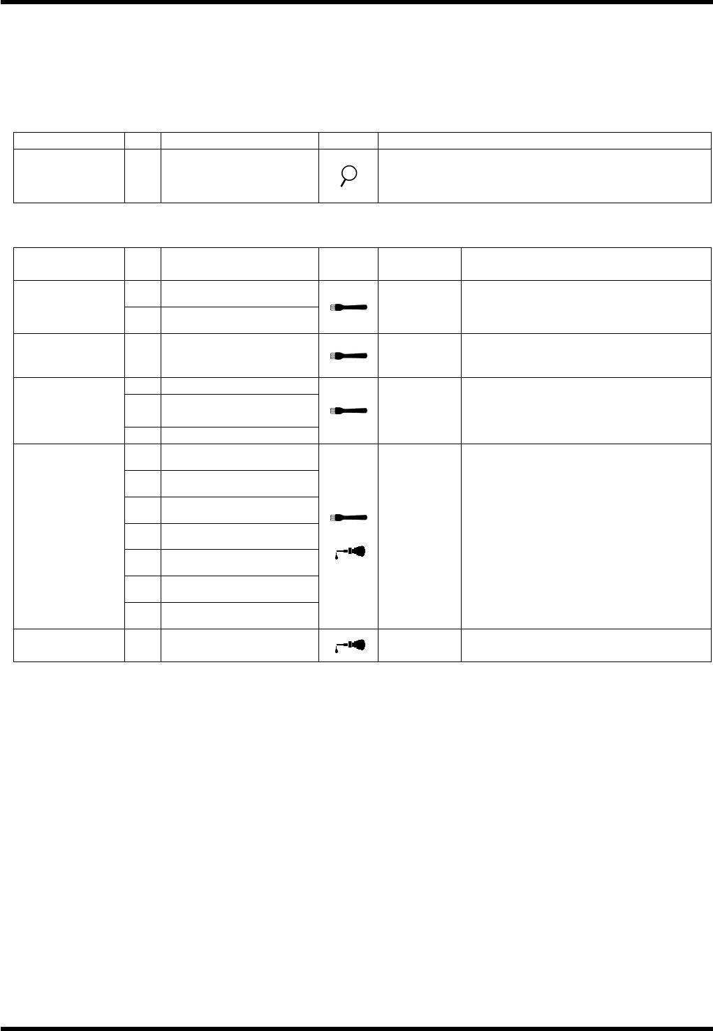
7.2.3 Monthly Check Items
The following tables summarize the periodic inspection items that are to be performed monthly.
For the details of inspection positions and lubrication method, refer to the subsequent sections.
Numbers in the Unit column show the relevant sections to be referred to.
Inspection (Monthly)
Unit No.
Item Task Description
7.3.4
Transfer Arm
Interlock Unit
a.
Roller
Make sure that the cam follower turns smoothly.
Oiling (Monthly)
Unit No.
Item Task
Oiling
volume
Description
1.
Ball screw (X)
7.3.1
X-Y Table
2.
Ball screw (Y)
3 cm
3
each
Position: Thread
7.3.4
Transfer Arm
Interlock Unit
1.
Cam follower
0.1 cm
3
Position: Running surface
2.
Shifter A, B
3.
Seam between shifter
A and B
7.4.1
Insertion Head
4.
Ball spline
0.5cm
3
Remove all dirt adhering on the
surface completely and apply a thin
coat of grease.
1.
Cam
2.
Lever
3.
Slider
4.
Lever (2)
5.
Lever (3)
6.
Spring hook
7.5.1
Feeder
7.
Tape cutter
0.5 cm
3
Remove all dirt adhering on the
surface completely and apply a thin
coat of grease.
Apply 1 or 2 drops of the machine oil
to the shafts of the rollers.
7.7.1
Upper Anvil
1.
Movable blade sliding
surface
1 to 2
drops
Apply 1 or 2 drops of the machine oil
on the Movable blade sliding surface.