Maintenance Manual.pdf - 第135页
RL131 MAINTENANCE MANUAL 7.2 Periodic Ins pection Ite ms DA8MEC-Z0-020-A 0 7.2-6 7.2.4 Trimonthly Check Items The following tabl e summ arizes the periodic inspection items that are t o be perfor med trim onthly. For the…
RL131
MAINTENANCE MANUAL
7.2 Periodic Inspection Items
DA8MEC-Z0-020-A0
7.2-5
7.2.3 Monthly Check Items
The following tables summarize the periodic inspection items that are to be performed monthly.
For the details of inspection positions and lubrication method, refer to the subsequent sections.
Numbers in the Unit column show the relevant sections to be referred to.
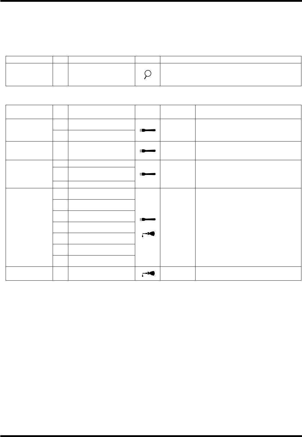
Inspection (Monthly)
Unit No.
Item Task Description
7.3.4
Transfer Arm
Interlock Unit
a.
Roller
Make sure that the cam follower turns smoothly.
Oiling (Monthly)
Unit No.
Item Task
Oiling
volume
Description
1.
Ball screw (X)
7.3.1
X-Y Table
2.
Ball screw (Y)
3 cm
3
each
Position: Thread
7.3.4
Transfer Arm
Interlock Unit
1.
Cam follower
0.1 cm
3
Position: Running surface
2.
Shifter A, B
3.
Seam between shifter
A and B
7.4.1
Insertion Head
4.
Ball spline
0.5cm
3
Remove all dirt adhering on the
surface completely and apply a thin
coat of grease.
1.
Cam
2.
Lever
3.
Slider
4.
Lever (2)
5.
Lever (3)
6.
Spring hook
7.5.1
Feeder
7.
Tape cutter
0.5 cm
3
Remove all dirt adhering on the
surface completely and apply a thin
coat of grease.
Apply 1 or 2 drops of the machine oil
to the shafts of the rollers.
7.7.1
Upper Anvil
1.
Movable blade sliding
surface
1 to 2
drops
Apply 1 or 2 drops of the machine oil
on the Movable blade sliding surface.
RL131
MAINTENANCE MANUAL
7.2 Periodic Inspection Items
DA8MEC-Z0-020-A0
7.2-6
7.2.4 Trimonthly Check Items
The following table summarizes the periodic inspection items that are to be performed trimonthly.
For the details of inspection positions and lubrication method, refer to the subsequent sections.
Numbers in the Unit column show the relevant sections to be referred to.
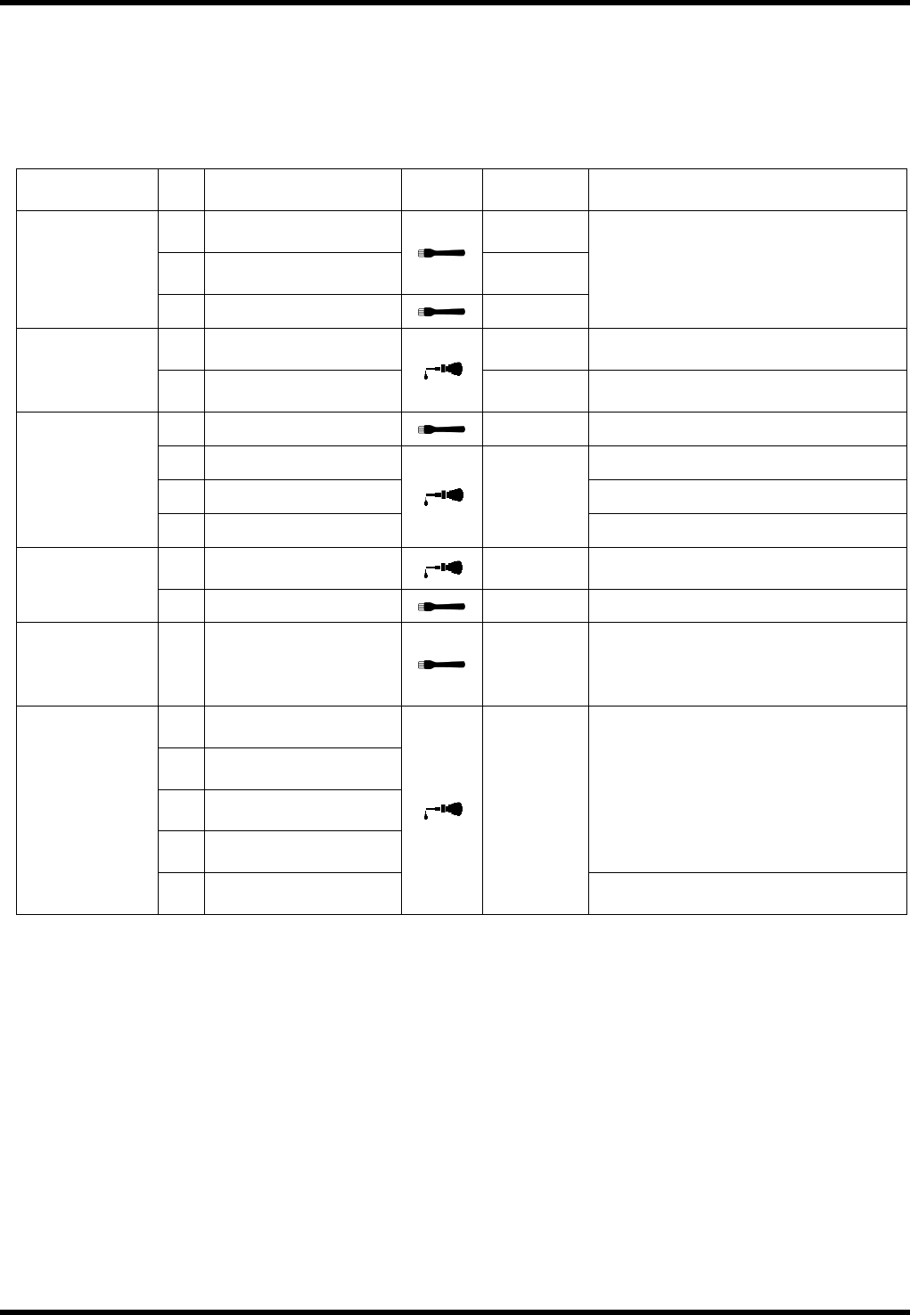
Oiling (3 Months)
Unit No.
Item Task
Oiling
volume
Description
3.
LM guide (X)
2 cm
3
each
4.
LM guide (Y)
2 cm
3
each
7.3.1
X-Y Table
5.
LM guide
0.25 cm
3
Position: Rail surface
1.
Shaft rotor
1 to 2
drops
7.3.2
Positioner
2.
Shaft sliding surface
Moderate
amount
Wipe it with a cloth dampened with
machine oil.
1.
Shaft surface
0.25 cm
3
Apply a thin coat of grease.
2.
Link pivot
3.
Belt roller Position: Each shaft hole
7.3.3
Loader/Unloader
4.
Cylinder support
1 to 2
drops
1.
Lever support
1 to 2
drops
7.3.5
PCB Transfer
Unit
2.
Shaft
0.25 cm
3
Position: Sliding surface
7.4.6
Main Drive Unit
1.
Gear surface
0.5 cm
3
Remove all dirt adhering on the
surface completely and apply a thin
coat of grease to the engagement
portion of the gear.
1.
Collar
(2 positions: left/right)
2.
Collar
(2 positions: left/right)
3.
Collar
(2 positions: left/right)
4.
Collar
(2 positions: left/right)
Position: Sliding surface
7.9.1
Cover Unit
5.
Hinge
1 to 2
drops each
Position: Clearances of 25 mm
intervals

RL131
MAINTENANCE MANUAL
7.2 Periodic Inspection Items
DA8MEC-Z0-020-A0
7.2-7
7.2.5 5,000-hour Check Items
The following table summarizes the periodic inspection items that are to be performed every 5000 hours.
For the details of inspection positions and lubrication method, refer to the subsequent sections.
Numbers in the Unit column show the relevant sections to be referred to.
Oiling (Every 5000 hours)
Unit No.
Item Task
Oiling
volume
Description
7.4.2
Insertion Drive
Unit
3.
Worm reduction gear
0.18 L
(Inside the
reduction
gear)
Replace the lubricant inside the
reduction gear.
Drain oil: Open the lock valve at the
bottom of the worm
reduction gear to drain old
oil.
Feed oil: After draining oil, pour new
oil from the oil port at the
top of the worm reduction
gear. (up to the middle of
the check window)
7.6.4
Part Processing
Drive Unit
3.
Worm reduction gear
0.18 L
(Inside the
reduction
gear)
Replace the lubricant inside the
reduction gear.
Drain oil: Open the lock valve at the
bottom of the worm
reduction gear to drain old
oil.
Feed oil: After draining oil, pour new
oil from the oil port at the
top of the worm reduction
gear. (up to the middle of
the check window)
7.7.2
Anvil Drive Unit
3.
Worm reduction gear
0.18 L
(Inside the
reduction
gear)
Replace the lubricant inside the
reduction gear.
Drain oil: Open the lock valve at the
bottom of the worm
reduction gear to drain old
oil.
Feed oil: After draining oil, pour new
oil from the oil port at the
top of the worm reduction
gear. (up to the middle of
the check window)