Maintenance Manual.pdf - 第177页
RL131 MAINTENANCE MANUAL 8. MAINTENANCE GU IDE DA8MEC-83-A A0-A0 8-4
RL131
MAINTENANCE MANUAL
8. MAINTENANCE GUIDE
DA8MEC-83-AA0-A0
8-3
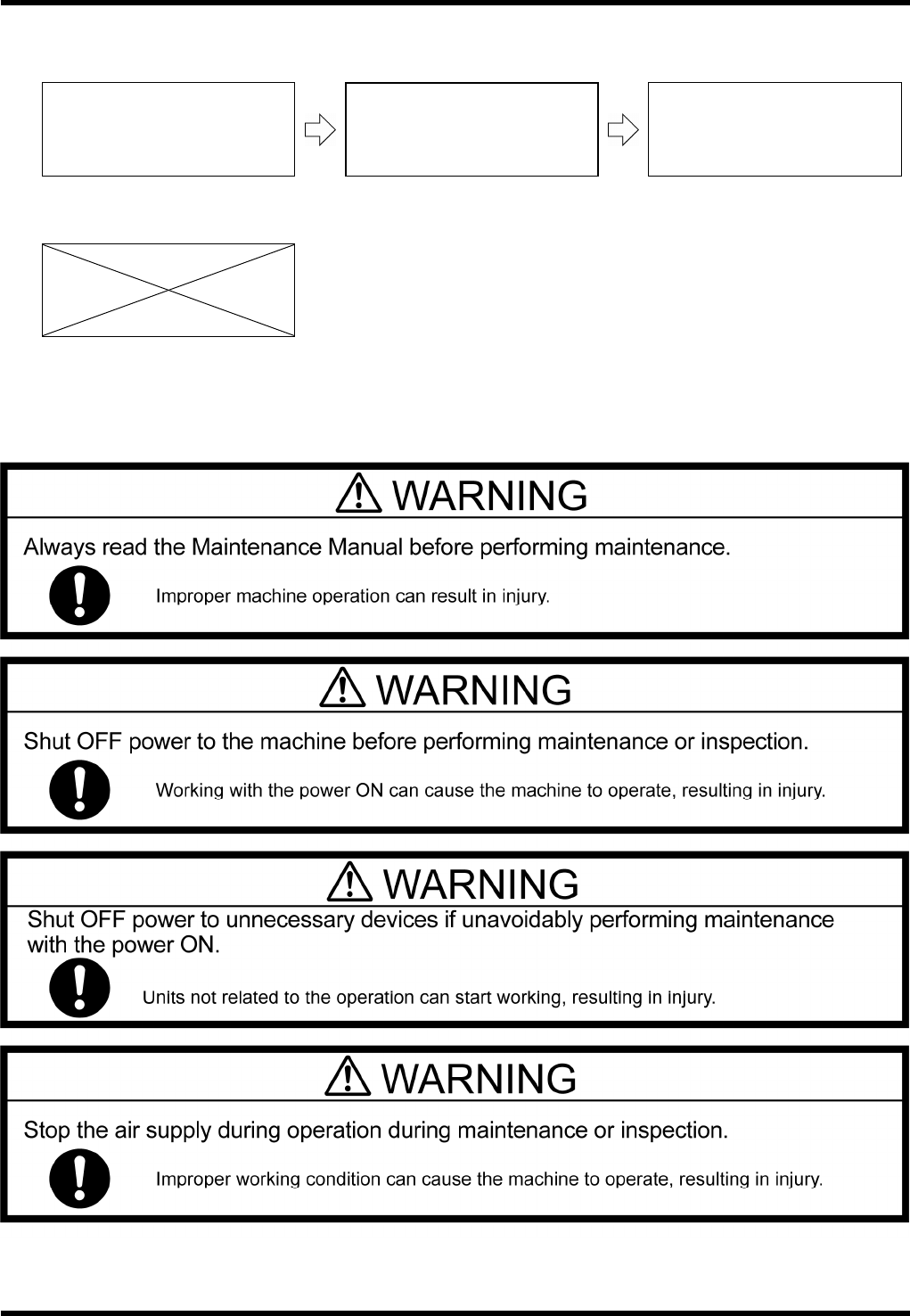
Related Works in Sequence
This chapter presents the relations among the maintenance works as shown in the following:
Work which should have been
completed in advance
Work explained in the section
Work which should be carried out
next
When there is no works to be done before or after the work explained in the section.
Safety Precautions
Before conducting inspection, read ‘Mtn. / SAFETY PRECAUTIONS’ thoroughly.

RL131
MAINTENANCE MANUAL
8. MAINTENANCE GUIDE
DA8MEC-83-AA0-A0
8-4

RL131
MAINTENANCE MANUAL
8.1 Insertion Chuck
DA8MEC-W4-400-A0
8.1-1
8.1. Insertion Chuck
DA8MEC-W4-400-A0
8.1.1 Adjusting Eccentricity of the Insertion Chuck
Unit No. N610052020AA
8.1.1 Adjusting Eccentricity of the
Insertion Chuck
8.1.2 Adjusting Height of the
Insertion Chuck
Adjusting Eccentricity
1.
1. Turn the power ON to return the machine to its origin.
2. Open the front cover.
3. Loosen the fitting bolt of the head cover and detach the
head cover from the head.
4. Turn ON the maintenance switch.
5. Press <ENABLING> + <START> to clear the error.
6. Rotate the handwheel to set the cycle timer to 0°.
7. Set an electronic component jig upside down.
Jig No.: X01A08006
8. Press [Machine Adjustment] [qH axis servo free].
9. Turn the belt of the insertion head manually to check the
eccentricity.
If decentered, proceed to the following steps.
10. Free the M3 bolt (1).
11. Free the lock screw at the back of the fine
adjustment screw (A).
12. Adjust the eccentricity in the vertical direction by
rotating the fine adjustment screw (A).
13. Free the set screw (1).
14. Adjust the eccentricity in the vertical direction by
rotating the fine adjustment screw (B).
=REMARKS=
Make eccentricity check visually or by using
the dial gauge’s probe set on the
component jig that has been set upside
down in the chuck.
The fine adjustment screws move in the
vertical direction with respect to the unit. However, check the initial mounting plane and condition
before loosening them. They may shift toward other direction.
15. Retighten the fitting bolt of the head cover to reattach the head cover.
16. Turn OFF the maintenance switch.
Handwheel
Normal catching Reverse catching
Electronic
component jig
Rotate the head by hand
to check for eccentricity
Setting electronic component jig
Fine adjustment
screw (A)
Lock screw
Set screw
Fine adjustment
screw (B)
M3 bolt