Maintenance Manual.pdf - 第186页
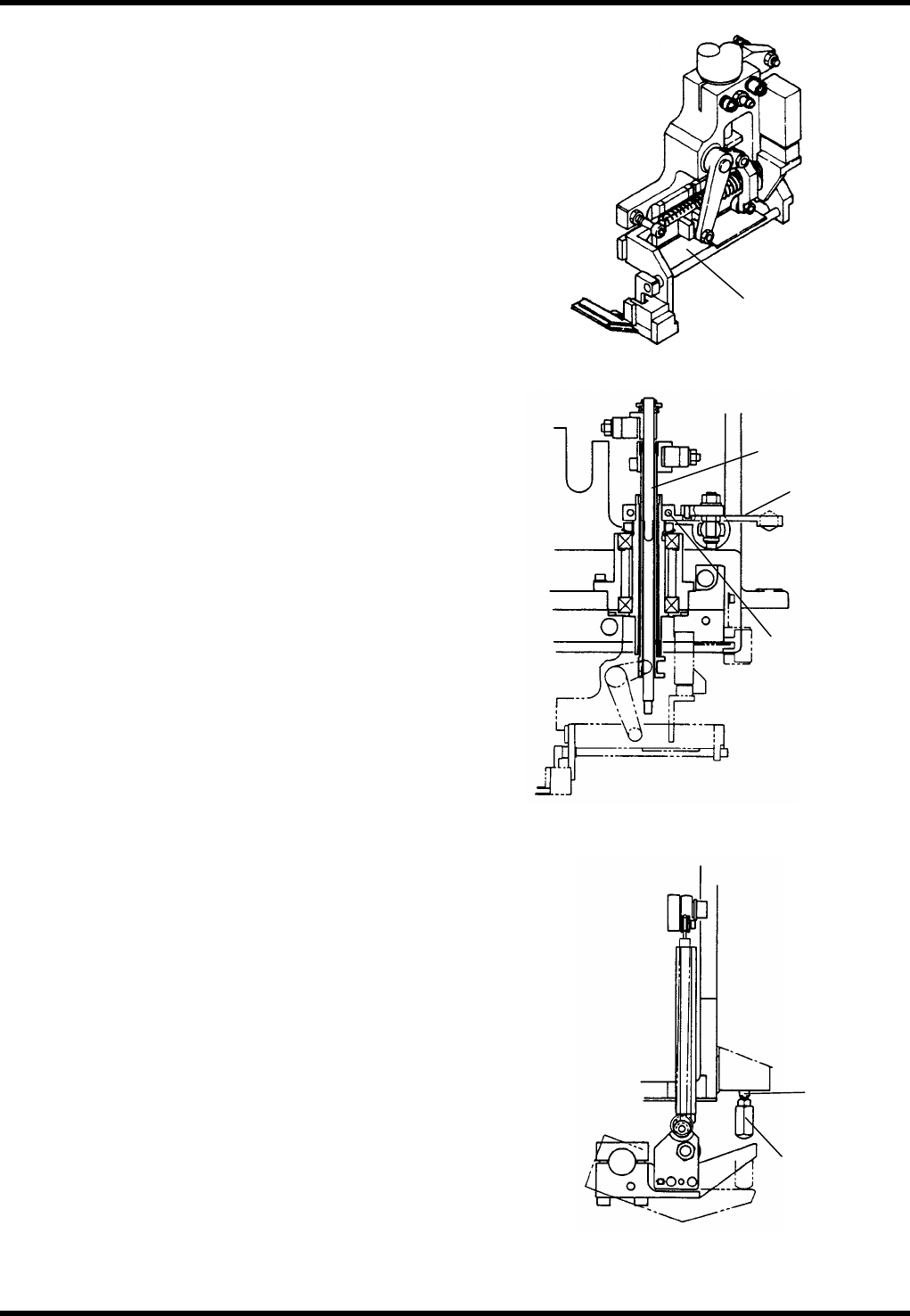
RL131 MAINTENANCE MANUAL 8.2 Trans fer Chuck DA8MEC-W 4-400-A0 8.2-5 8.2.4 A dj usting Cle arance betw een Pallet and Transfer Chuc k Unit No. X02G44000AB 8.2.4 Adjusting Cle arance between Pallet and Tran sfer Chuck 8.2…
RL131
MAINTENANCE MANUAL
8.2 Transfer Chuck
DA8MEC-W4-400-A0
8.2-4
Transfer chuck centering (1)
4.
1. Rotate the handwheel to set the cycle timer to 15°.
2. Loosen the bolt (F) of the lever (E) and move the
transfer chuck to the position where an electronic
component jig can be transferred smoothly to the
insertion chuck claw.
=REMARKS=
If fine adjustment cannot be made, loosen the bolt
(D) of the transfer chuck and adjust again.
3. Retighten the bolt (F) to lock in place.
4. Fit the return spring
5. Slide the transfer chuck again to the handling position
of the insertion chuck and check that an electronic
component jig can be transferred smoothly to the
insertion chuck claw. If transferred, the adjustment is
completed.
=REMARKS=
If an electronic component jig can be transferred
smoothly, repeat steps 1 to 5 again.
Transfer chuck centering (2) - recovery
adjustment
5.
1. Rotate the handwheel to set the cycle timer to 135°.
2. Turn ON <TRANSFER HEAD SWING CYLINDER> on
the sub-control panel.
3. Loosen the nut (G) and adjust so that the lever touches
the end rod (H). Then retighten the nut (G).
4. Turn OFF <TRANSFER HEAD SWING CYLINDER>.
=REMARKS=
If the recovery adjustment fails, repeat steps 1 to 4
again.
Shaft (C)
Lever (E)
Bolt (F)
Transfer head
Transfer head
Nut (G)
End rod (H)
Transfer chuck
Adjusting transfer chuck
RL131
MAINTENANCE MANUAL
8.2 Transfer Chuck
DA8MEC-W4-400-A0
8.2-5
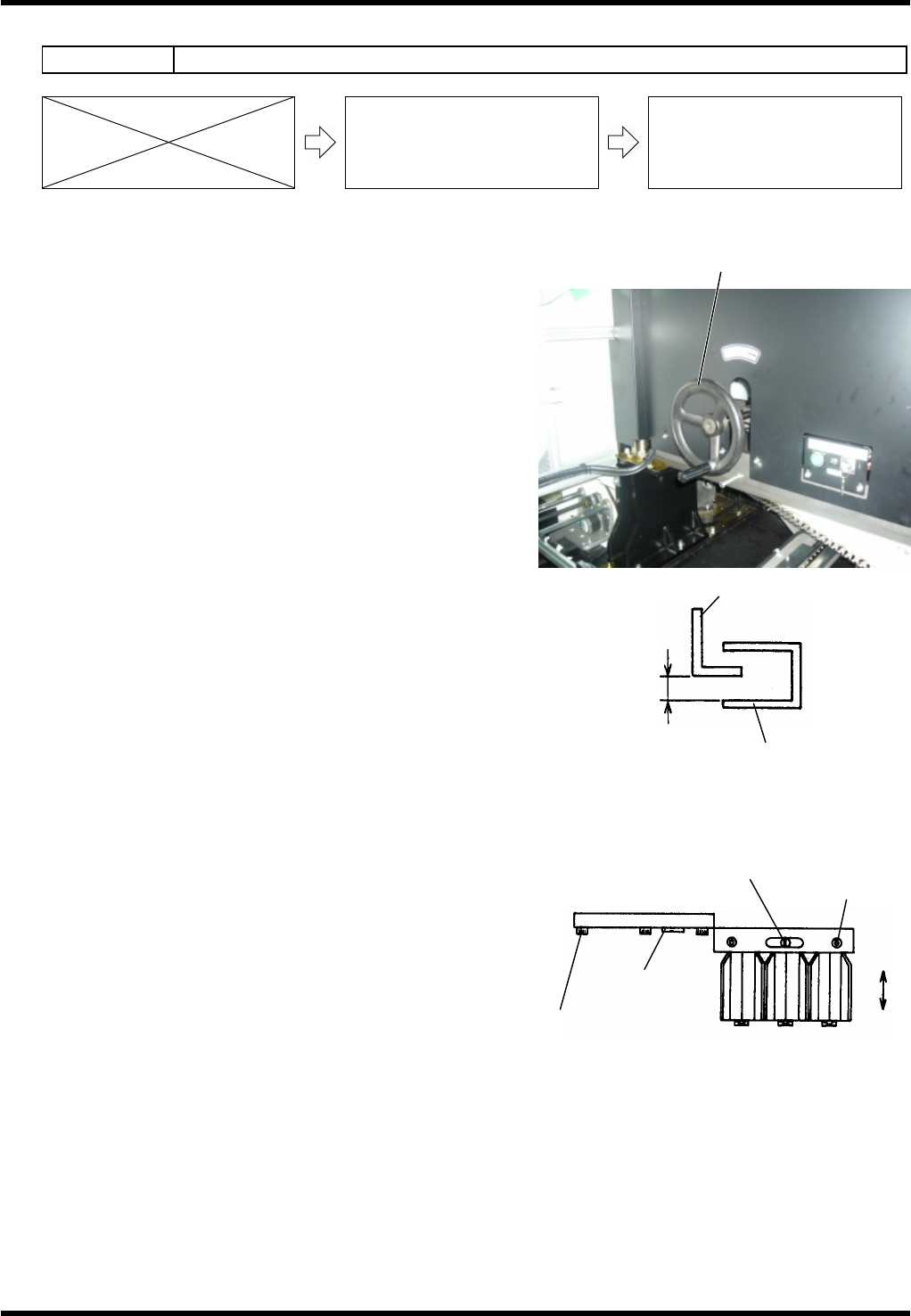
8.2.4 Adjusting Clearance between Pallet and Transfer Chuck
Unit No. X02G44000AB
8.2.4 Adjusting Clearance between
Pallet and Transfer Chuck
8.2.5 Adjusting Handling Accuracy of
Electronic Components (Transfer
Chuck from Pallet)
Adjusting clearance
6.
1. Rotate the handwheel to set the cycle timer to 0°.
2. Turn OFF <Trans head back> on the sub-control panel.
3. Rotate the handwheel to set the cycle timer to around
190 to 200°.
4. Check that the clearance between the transfer chuck
claw and pallet is 1.2 mm.
If not, proceed to the steps below.
5. Loosen the bolt (A) (M82).
6. Rotate the fine adjustment screw (A) and move the
pallet until the clearance between the pallet and
transfer chuck claw is 1.2 mm.
7. Retighten the bolt (A) (M82) to lock in place.
8. Check that the clearance between the transfer chuck
claw and pallet again.
If the clearance is 1.2 mm, the adjustment is
completed.
=REMARKS=
If the clearance is not 1.2 mm, repeat steps 1 to 8
again.
Handwheel
Transfer chuck claw
Checking clearance
1.2 mm
Pallet
Adjusting pallet
Bolt (B)
(M83)
Fine adjustment
screw (B)
Fine adjustment
screw (A)
Bolt (A)
(M82)
RL131
MAINTENANCE MANUAL
8.2 Transfer Chuck
DA8MEC-W4-400-A0
8.2-6
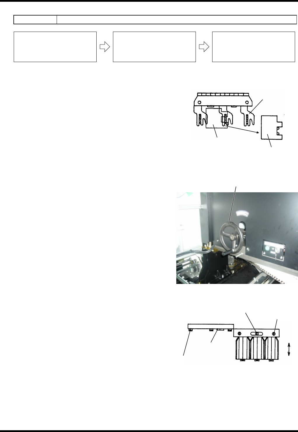
8.2.5 Adjusting Handling Accuracy of Electronic Components
Unit No. X02G44000AB
8.2.4 Adjusting Clearance between
Pallet and Transfer Chuck
8.2.5 Adjusting Handling Accuracy of
Electronic Components (Transfer
Chuck from Pallet)
8.2.6 Adjusting Pallet
Adjusting handling accuracy (Transfer chuck from pallet)
7.
1. Fit the F type jig to the base of the pallet and insert an
electronic component jig in between the F type jig and
pallet.
2. Turn OFF <Trans head back> on the sub-control panel.
3. Rotate the handwheel to check that the transfer chuck
claws grip the leads of the electronic component jig on
the pallet straight and proper. If not, follow the steps
below.
=REMARKS=
Make sure the chuck claws grip the leads when the
cycle time is between 190° and 200°.
4. Loosen the bolt (B) (M83).
5. Rotate the fine adjustment screw (B) and move the
pallet to the position where the transfer chuck claws
can grip the component jig on the pallet straight and
proper.
6. Retighten the bolt (B) (M83) to lock in place.
7. Rotate the handwheel and recheck that chuck claws
can grip the component jig on the pallet straight and
proper. If the chuck claws grip it successfully,
adjustment is completed.
=REMARKS=
If gripping fails, repeat the steps 1 to 7 again.
Handwheel
Setting F type jig
Lead in 0.5-mm pitch
Pallet
F type jig
Adjusting pallet
Bolt (B)
(M83)
Fine adjustment
screw (B)
Fine adjustment
screw (A)
Setting machine offset