Maintenance Manual.pdf - 第192页
RL131 MAINTENANCE MANUAL 8.4 Anvil Unit DA8MEC-W 4-400-A0 8.4-1 8.4. Anvil Unit DA8MEC- W 4-400-A0 8.4.1 A dj usting/Re placing Fixe d and M ovable Blades of Anvil Unit No. X02G51000AA 8.4.1 Adjusting/Repla c ing Fixe d …

RL131
MAINTENANCE MANUAL
8.3 Insertion Head Unit
DA8MEC-W4-400-A0
8.3-2
RL131
MAINTENANCE MANUAL
8.4 Anvil Unit
DA8MEC-W4-400-A0
8.4-1
8.4. Anvil Unit
DA8MEC-W4-400-A0
8.4.1 Adjusting/Replacing Fixed and Movable Blades of Anvil
Unit No. X02G51000AA
8.4.1 Adjusting/Replacing Fixed and
Movable Blades of Anvil
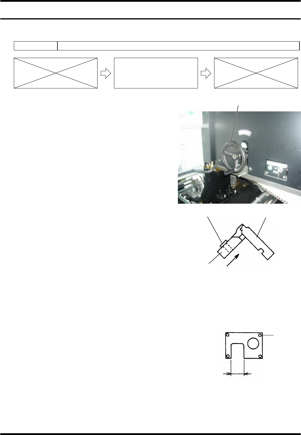
Removing Anvil Unit
1.
1. Set the servo free.
2. Remove the anvil lock bolt (M5x2).
3. While raising the clinch lever slightly, lift the anvil and
rotate it counterclockwise. Then, remove the anvil when
the yellow marks meet.
Replacing Blades
2.
1. Remove the bolts A (x4) from the anvil blade lid, then
remove the movable blade.
2. Remove the bolt B (M4x1) and replace the fixed blades
with new ones.
3. Set new fixed blades and secure them with the bolt A
(x4) on the anvil blade cover.
4. Check the movable blades moves smoothly.
Replacing/Adjusting Anvil Fixed Blades and
Movable Blades
3.
1. Turn the handwheel to adjust the cycle timer at 258° ± 1°.
2. Based on the movable blade, attach the fixed blade and
secure it with the bolt (M4x1)
=REMARKS=
The anvil blade cover with narrow A measurement is
for a single movable blade side, and the longer is for
double movable blade side.
3. The height of the anvil must be 0.05 mm higher than the
gap between PCB holder and reference rail.
=REMARKS=
Be aware that the height of the anvil changes with the
fixed blade attachment.
Handwheel
Bolt A
A
Anvil blade cover
Bolt B (M4
´
1)
Fixed
blade
Movable blade
Shift the fixed blade to attach it
to the movable blade.
Adjusting fixed and movable
blades
RL131
MAINTENANCE MANUAL
8.4 Anvil Unit
DA8MEC-W4-400-A0
8.4-2
8.4.2 Adjusting Anvil Clinch Stroke
Unit No. N610074515AA
8.4.1 Adjusting/Replacing Fixed and
Movable Blades of Anvil
8.4.2 Adjusting Anvil Clinch Stroke
8.4.3 Adjusting the Height of
Backup Pins
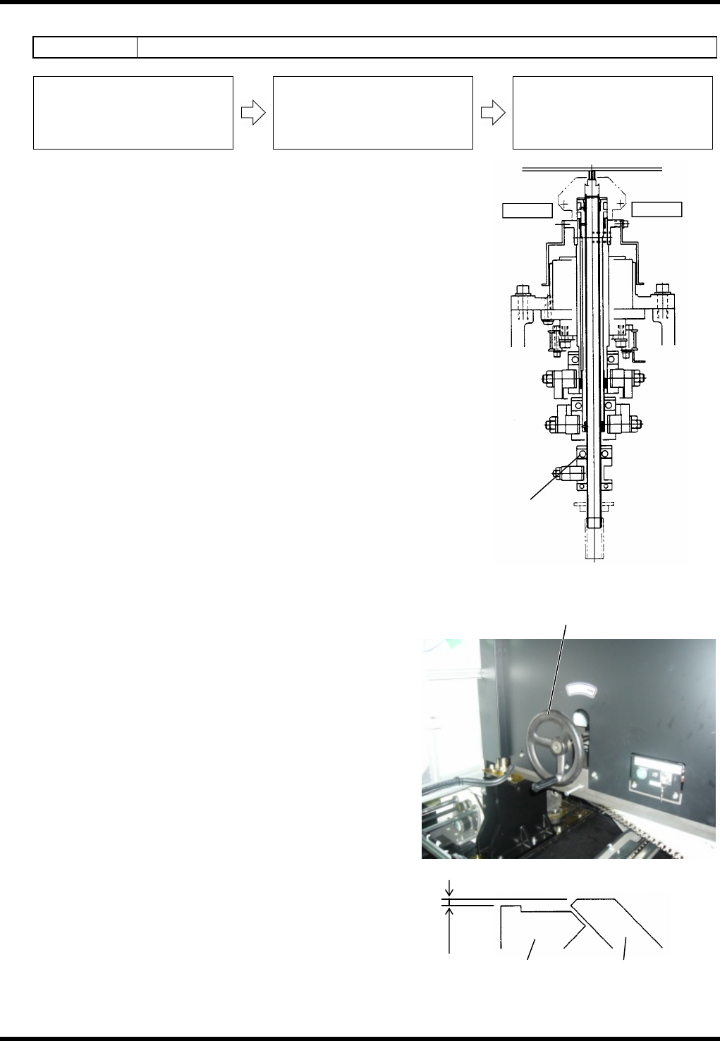
Adjusting the Clinch Stroke
4.
1. Loosen the retaining bolt (A) of the anvil lower part.
2. Rotate the handwheel to set the cycle timer at the
position 258°±1° at which the clinch has fully moved
forward.
Set the needle of the dial gauge to the fixed blades.
3. Slide the dial gauge aside until it touches the movable
blades, then adjust its height to be 0.45 ±0.05 mm
higher than the fixed blades.
4. Retighten the retaining bolt (A) of the anvil lower part to
secure in place.
5. Turn the handwheel 360° and check, again, the gap
between fixed and movable blades.
Adjustment is completed if the gap is 0.45 ±0.05 mm.
=REMARKS=
The gap is not 0.45 ±0.05 mm, repeat the steps
from 1 to 5 again.
As for clinch stroke, the gap between fixed
blade PCB holder and the movable blade must
be 0.45 ±0.05 mm.
Handwheel
Bolt (A)
Anvil lower part
Fixed blade Movable blade
0.45
±
0.05 mm
Adjusting fixed and
movable blades