Maintenance Manual.pdf - 第194页
RL131 MAINTENANCE MANUAL 8.4 Anvil Unit DA8MEC-W 4-400-A0 8.4-3 8.4.3 A dj usting t he Height of Back up Pins Unit No. N610074515AA 8.4.2 Adjusting Anvil Cl inc h Stroke 8.4.3 Adjusting the Heigh t of Backup Pins Adjus…
RL131
MAINTENANCE MANUAL
8.4 Anvil Unit
DA8MEC-W4-400-A0
8.4-2
8.4.2 Adjusting Anvil Clinch Stroke
Unit No. N610074515AA
8.4.1 Adjusting/Replacing Fixed and
Movable Blades of Anvil
8.4.2 Adjusting Anvil Clinch Stroke
8.4.3 Adjusting the Height of
Backup Pins
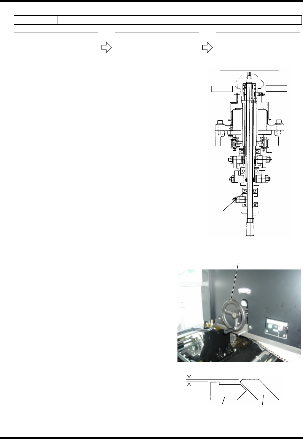
Adjusting the Clinch Stroke
4.
1. Loosen the retaining bolt (A) of the anvil lower part.
2. Rotate the handwheel to set the cycle timer at the
position 258°±1° at which the clinch has fully moved
forward.
Set the needle of the dial gauge to the fixed blades.
3. Slide the dial gauge aside until it touches the movable
blades, then adjust its height to be 0.45 ±0.05 mm
higher than the fixed blades.
4. Retighten the retaining bolt (A) of the anvil lower part to
secure in place.
5. Turn the handwheel 360° and check, again, the gap
between fixed and movable blades.
Adjustment is completed if the gap is 0.45 ±0.05 mm.
=REMARKS=
The gap is not 0.45 ±0.05 mm, repeat the steps
from 1 to 5 again.
As for clinch stroke, the gap between fixed
blade PCB holder and the movable blade must
be 0.45 ±0.05 mm.
Handwheel
Bolt (A)
Anvil lower part
Fixed blade Movable blade
0.45
±
0.05 mm
Adjusting fixed and
movable blades
RL131
MAINTENANCE MANUAL
8.4 Anvil Unit
DA8MEC-W4-400-A0
8.4-3
8.4.3 Adjusting the Height of Backup Pins
Unit No. N610074515AA
8.4.2 Adjusting Anvil Clinch Stroke
8.4.3 Adjusting the Height of
Backup Pins
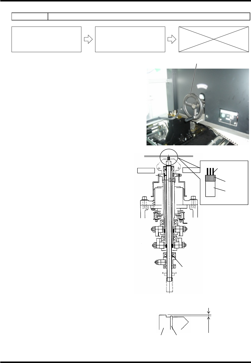
Adjusting the Height of Backup Pins
5.
1. Turn the handwheel to set the cycle timer at 150°.
2. Measure the heights of anvil PCB receiver and
backup pin and check if the difference is between
0 and -0.1 mm.
Proceed to the next step if the difference is not
within the above range.
3. Loosen the retaining bolt (B) of the anvil lower part
and raise the backup pin to adjust the height
difference with the anvil PCB receiver to between
0 and 0.1 m.
4. Retighten the retaining bolt (A) of the anvil lower
part to secure in place.
5. Turn the handwheel 360° and measure, again, the
heights of the anvil PCB receiver and the backup
pin.
Adjustment is completed if the difference in height
is 0 to –0.1 mm.
=REMARKS=
If the difference in height is not 0 to –0.1 mm,
repeat the steps from 1 to 5 again.
Replacing the Backup Pins
6.
1. Remove the cap which secures the backup pins.
2. Pull out the pins from the shaft.
3. Place new backup pins, then tighten the cap to
secure them.
Adjusting the height of backup pins
0 to 01 mm
Fixed blade Backup pin
Handwheel
Bolt (B)
Anvil lower part
Backup pin
Cap
Shaft

RL131
MAINTENANCE MANUAL
8.4 Anvil Unit
DA8MEC-W4-400-A0
8.4-4