Maintenance Manual.pdf - 第199页
RL131 MAINTENANCE MANUAL 8.6 Recognition and Light ing Unit DA8MEC-W 0-400-A0 8.6-2 Proce dure for Cleaning the Floodlight =PREP ARATION= 1. Tools for c leaning 2. Dry, soft cloth 2. 1. Return the m achine to the origi…
RL131
MAINTENANCE MANUAL
8.6 Recognition and Lighting Unit
DA8MEC-W0-400-A0
8.6-1
8.6. Recognition and Lighting Unit
DA8MEC-W0-400-A0
8.6.1 Cleaning the Camera / Floodlight
Unit No. N610052084AA
8.6.1 Cleaning the Camera /
Floodlight
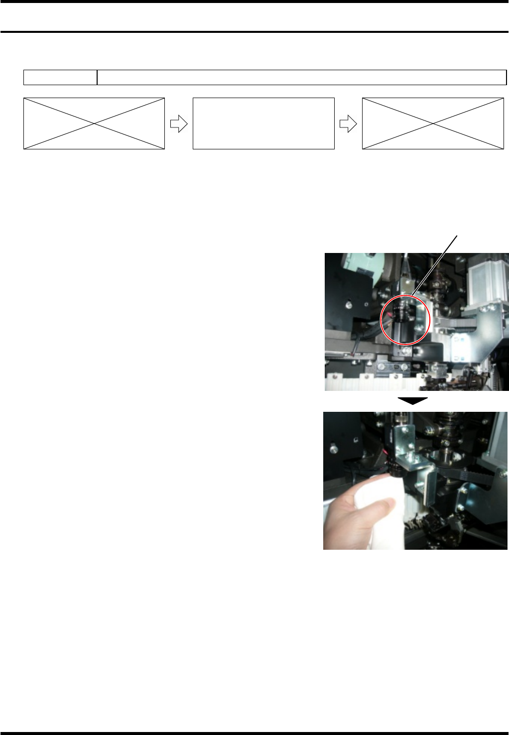
When “HOLE RECOG HOLE NOT IN SEARCH AREA” occurs during the PCB hole recognition, it is likely
that the lens of the recognition camera is dirty. Procedure for cleaning the lens is shown below.
Procedure for Cleaning the Camera
1.
1. Prepare tools for cleaning.
Dry, soft cloth
2. Return the machine to the origin, and then turn the <SERVO>
switch or power supply OFF.
3. Open the machine front cover.
4. Detach the front cover.
5. The camera is located to the left of the insertion head. As
shown in the right photo, access the camera from beneath
and wipe the lens with the soft cloth prepared in step 1.
6. Execute the PCB hole recognition again to check that “HOLE
RECOG HOLE NOT IN SEARCH AREA” does not occur.
=REMARKS=
Avoid the grease adherence on the lens.
Recognition camera
Insertion head
RL131
MAINTENANCE MANUAL
8.6 Recognition and Lighting Unit
DA8MEC-W0-400-A0
8.6-2
Procedure for Cleaning the Floodlight
=PREPARATION=
1. Tools for cleaning
2. Dry, soft cloth
2.
1. Return the machine to the origin, and then turn the <SERVO>
switch or power supply OFF.
2. Open the machine front cover.
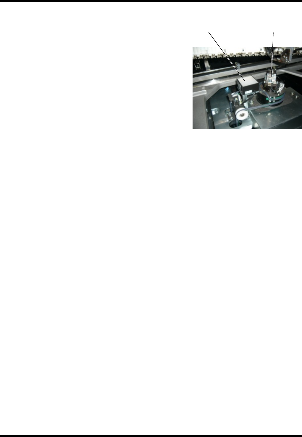
3. The floodlight is located to the right of the anvil unit as seen
from the machine front side. Wipe off any dirt or dust at the
top of the floodlight.
4. Execute the PCB hole recognition again to check that “HOLE
RECOG HOLE NOT IN SEARCH AREA” does not occur.
Anvil unit
Floodlight
RL131
MAINTENANCE MANUAL
8.7 Controller
DA8MEC-W0-600-A0
8.7-1
8.7. Controller
DA8MEC-W0-600-A0
8.7.1 Cleaning the CPU Box Fan Filter
Unit No.
8.6.1 Cleaning the CPU Box Fan
Filter
Procedure for Cleaning the Fan Filter
=PREPARATION=
1. Allen wrench
2. Phillips screwdriver
1.
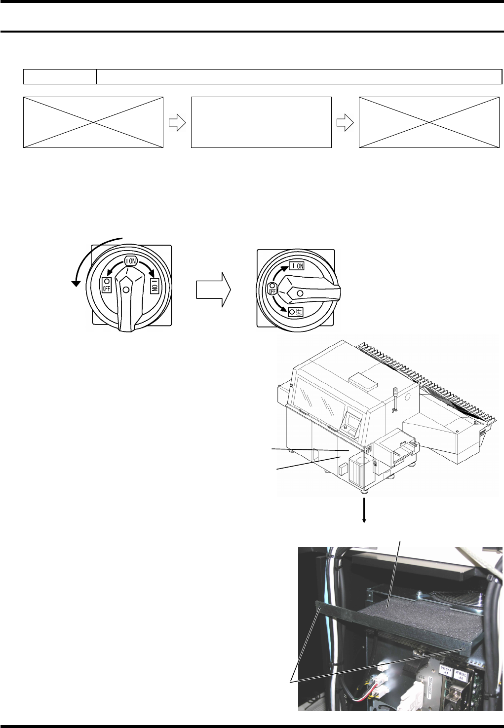
1. Set the main switch to OFF.
2. Remove the front cover.
3. Detach the control area cover.
4. Remove the cross slot screws
(x2) on top of the CPU box.
5. Remove the screws and take
out the CPU box fan filter, then
clean the filter using a vacuum
cleaner, etc.
=REMARKS=
After reinstalling the cleaned filter, check that there
is no interference between the fan and the filter.
To do this, turn ON the main switch and check for
any abnormal sound.
Also, check the fan rotation for any problem.
After making these checks, turn OFF the main
switch immediately.
6. Reattach the control area cover.
7. Reattach the front cover.
1
Turn
Front cover
Control area cover
(Inside)
CPU box fan filter
Cross slot
screw