Maintenance Manual.pdf - 第61页
RL131 MAINTENANCE MANUAL 3.2 Connectin g the Power Supply DA8MEC-11-020- A0 3.2-2 3.2.2 Connecting Factor y Po w er Suppl y w ith Main Power Sw itch Preparations Check that the power volta ge of the f actory falls with…
RL131
MAINTENANCE MANUAL
3.2 Connecting the Power Supply
DA8MEC-11-020-A0
3.2-1
3.2. Connecting the Power Supply
DA8MEC-11-020-A0
This section includes the method of connecting the power cable to the machine.
Refer to Wiring Diagram in the separate manual for more information.
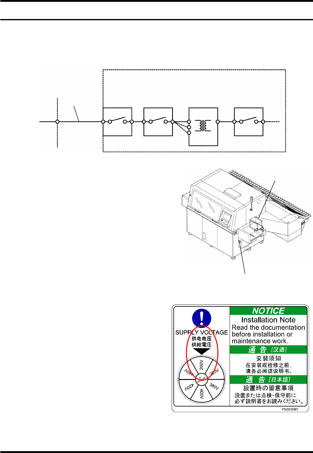
3.2.1 Overview
The RL131 is provided with a step-down transformer.
The machine is wired as in the following:
1) Main switch ® Breaker
2) Breaker ® Step-down transformer
3) Step-down transformer ® Subsequent equipment
The voltage of the step-down transformer is
factory-configured to the value specified by the
customer.
Connect the factory power supply (A) and the main
switch (B).
This cable should be provided by the user.
=REMARKS=
Should the voltage of factory power supply be
changed due to transfer of the machine, etc., the
voltage setting of the step-down transformer (C)
need be changed.
Factory power supply: Provide an appropriate
overcurrent protective fuse for the step-down
transformer.
Step-down transformer:
Can be switched to 480V, 420V, 400V, 380V,
220V and 200V.
Make sure that the voltage shown on the
SUPPLY VOLTAGE label agrees with the setting
of the factory power supply. (The label shown on
the right is an example of supply voltage of
200V.)
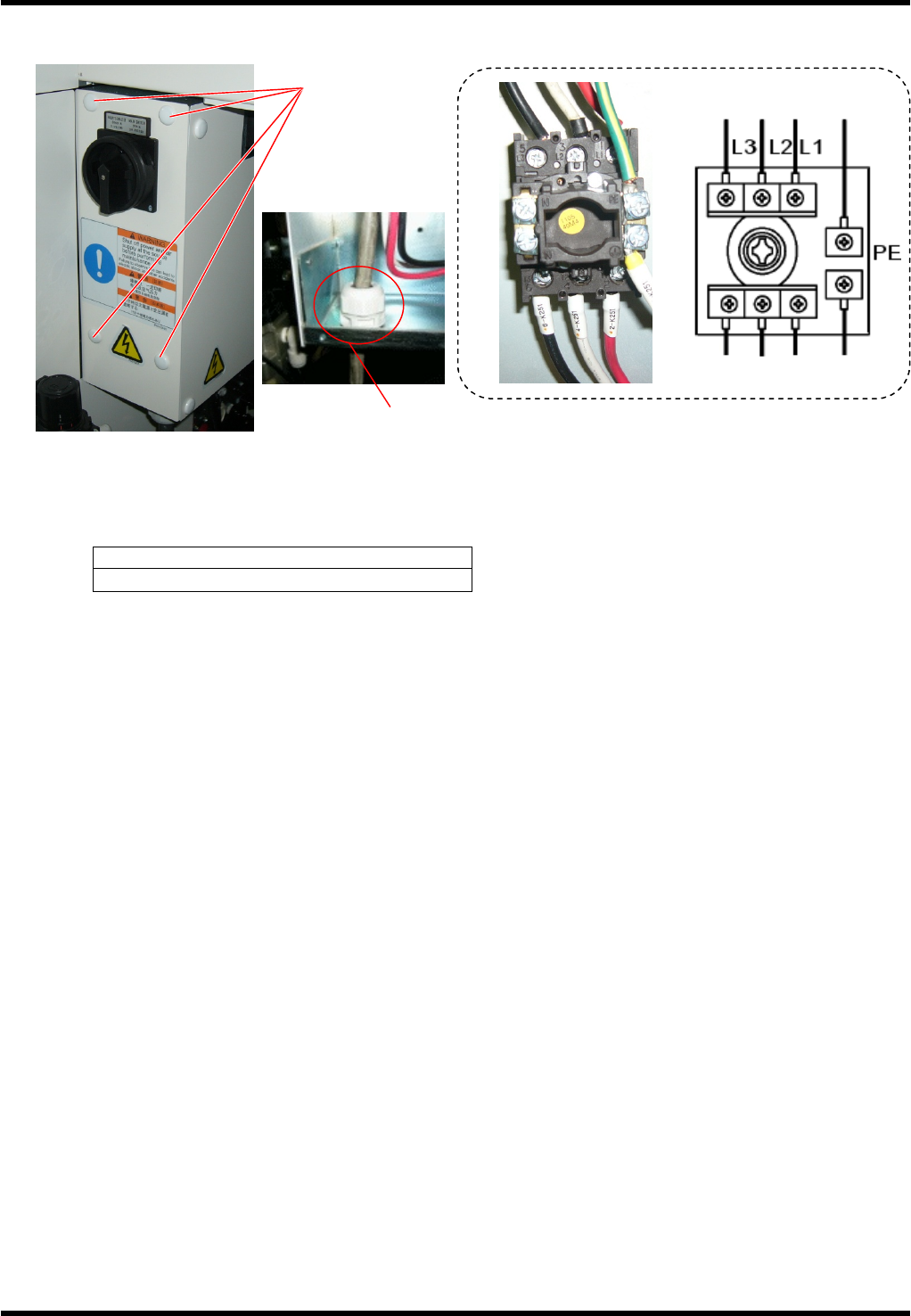
Ground terminal is labeled as PE.
Factory power supply
Machine
Main switch Breaker
Step-down
transformer
Breaker
Circuit protector
A
C
B
This cable
should be
provided by the
user.
D
Main switch
Step-down
transformer
RL131
MAINTENANCE MANUAL
3.2 Connecting the Power Supply
DA8MEC-11-020-A0
3.2-2
3.2.2 Connecting Factory Power Supply with Main Power Switch
Preparations
Check that the power voltage of the factory falls within the voltage range shown on the label of the
step-down transformer.
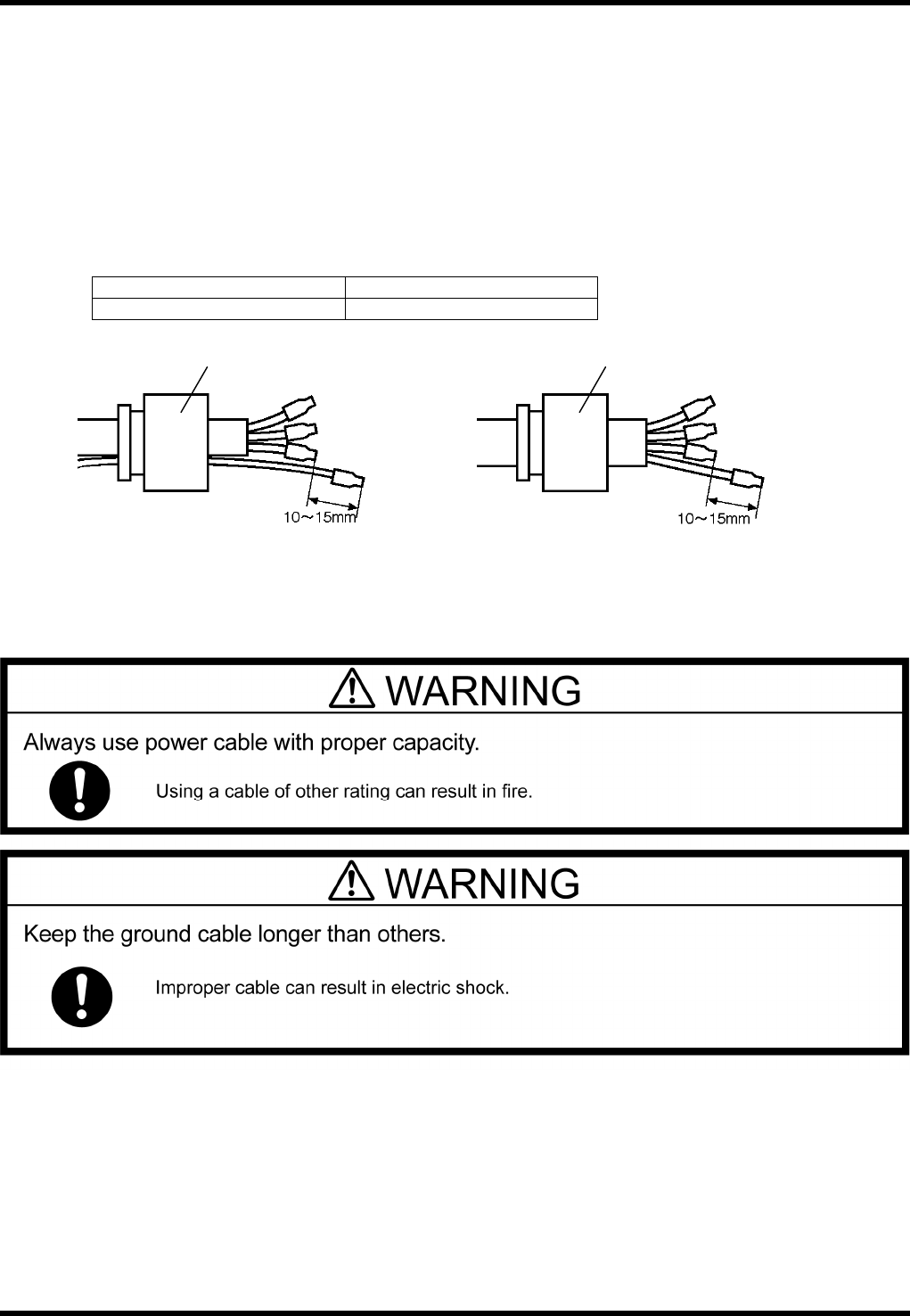
Use of captyre cable (Oil-resistant) is recommended for the power cable.
In order to fix the cable securely with the cable gland, prepare a cable with outer size of 18.5 to 20.5
mm.
It is recommended to use a yellow-and-green spiral stripe coating wire for the ground cable.
The conductor size should be equivalent to the supply power cable.
Use an H sleeve to avoid trouble caused by raveled core.
Recommended terminal Conductor size
H6/20 Weidmuller make AWG10 (6 mm
2
)
Cable gland
3-core cable and
1-core ground cable
L1
L2
L3
PE
Cable gland
4-core cable
L1
L2
L3
PE
RL131
MAINTENANCE MANUAL
3.2 Connecting the Power Supply
DA8MEC-11-020-A0
3.2-3
Connecting Cables
Turn OFF the power switch of the distribution panel.
Connect the distribution panel to the input terminals of the main switch by 3-core cable and one core
protective ground cable or 4-core cable (one for protective earth). The protective earth (PE) must be
connected.
Screw tightening torque
1.6 N×m
Fix the power cable securely with the cable gland (SC lock).
Check that the cable is not loosened under a tension of 100 N.
Inside of the machine
Factory power
Screw cramp x 4
Cable gland (SC lock)