00193786-01.pdf - 第15页
SIPLACE GEM SW Version GEM 505.01 HOST Interface Manual ©Siemens AG, all rights reserved page 15 of 236 1.9.2 Machine Areas of a SIPLACE HF/3 Machine The figure below provides a diagrammatic overview of the individual ar…
SIPLACE GEM SW Version GEM 505.01 HOST Interface Manual
Page 14 of 236 ©Siemens AG, all rights reserved
Equipment The SIPLACE with GEM/SECS II-Interface
Operator The person who physically has access to the equipment’s material port(s)
and control panel. This is the person who is operating the SIPLACE.
Host The computer which is connected to the equipment via the SECSII-interface
1.9 Machine Areas
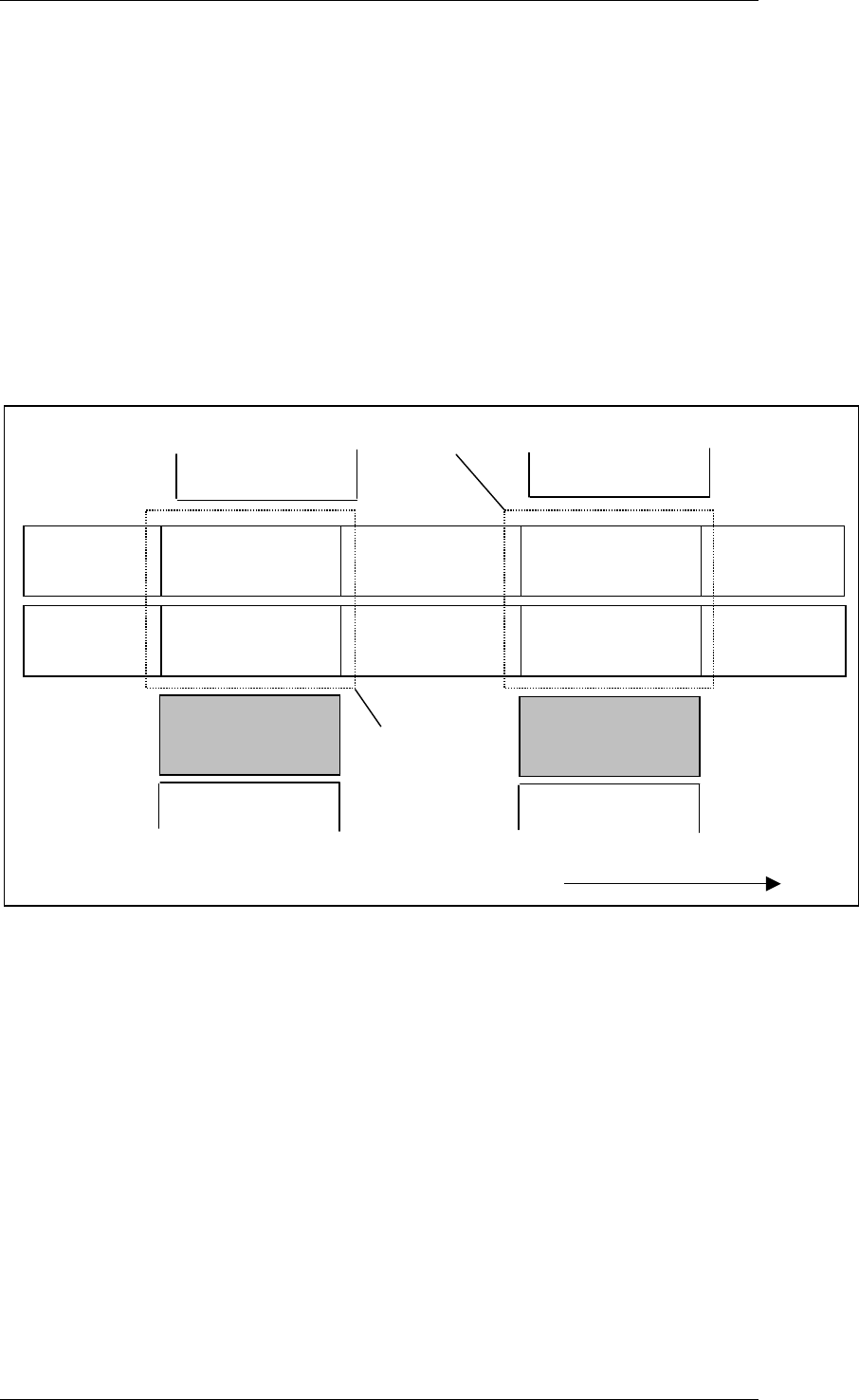
1.9.1 Machine Areas of a SIPLACE HF Machine
The figure below provides a diagrammatic overview of the individual areas of a
SIPLACE HF placement station.
TWIN-Input
conveyor
TWIN-First
Processing
conveyor
TWIN-Output
conveyor
Input
conveyor
First Processing
conveyor
Output
conveyor
Direction of transport
Conveyor 2
(left)
Conveyor 1
(right)
Gantry 3
Head 3
Location
3
Location
2
TWIN-Inter-
mediate conveyor
TWIN-Second
Processing
conveyor
Intermediate
conveyor
Second Processing
conveyor
Location
4
Gantry 1
Head 1
Location
1
Processing 1
Area
Processing 2
Area
SIPLACE GEM SW Version GEM 505.01
HOST Interface Manual
©Siemens AG, all rights reserved page 15 of 236
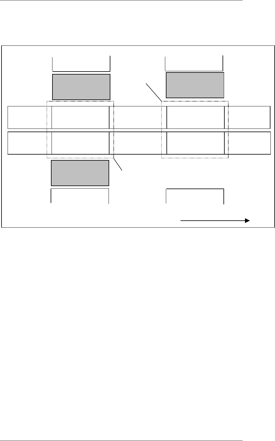
1.9.2 Machine Areas of a SIPLACE HF/3 Machine
The figure below provides a diagrammatic overview of the individual areas of a
SIPLACE HF/3 placement station.
TWIN-Input
conveyor
TWIN-First
Processing
conveyor
TWIN-Output
conveyor
Input
conveyor
First Processing
conveyor
Output
conveyor
Direction of transport
Conveyor 2
(left)
Conveyor 1
(right)
Location
3
Location
2
TWIN-Inter-
mediate conveyor
TWIN-Second
Processing
conveyor
Intermediate
conveyor
Second Processing
conveyor
Gantry 4
Head 4
Location
4
Gantry 1
Head 1
Location
1
Processing 1
Area
Processing 2
Area
Gantry 3
Head 3
SIPLACE GEM SW Version GEM 505.01 HOST Interface Manual
Page 16 of 236 ©Siemens AG, all rights reserved
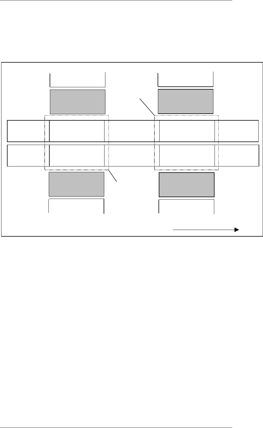
1.9.3 Machine Areas of a SIPLACE HS50 Machine
The figure below provides a diagrammatic overview of the individual areas of a
SIPLACE HS-50 placement station.
TWIN-Input
conveyor
TWIN-First
Processing
conveyor
TWIN-Output
conveyor
Input
conveyor
First Processing
conveyor
Output
conveyor
Direction of transport
Conveyor 2
(left)
Conveyor 1
(right)
Gantry 3
Head 3
Gantry 2
Head 2
Location
3
Location
2
TWIN-Inter-
mediate conveyor
TWIN-Second
Processing
conveyor
Intermediate
conveyor
Second Processing
conveyor
Gantry 4
Head 4
Location
4
Gantry 1
Head 1
Location
1
Processing 1
Area
Processing 2
Area