4OM-1050-002.pdf - 第148页
3.2 Error IDs and Controlled Areas Basic System of Error IDs An error ID is expressed by 6 digits (hexadecimal) as follows. Major Classification of “Operation Axis”, “Process Error”, and “T eaching Operation” Erro…
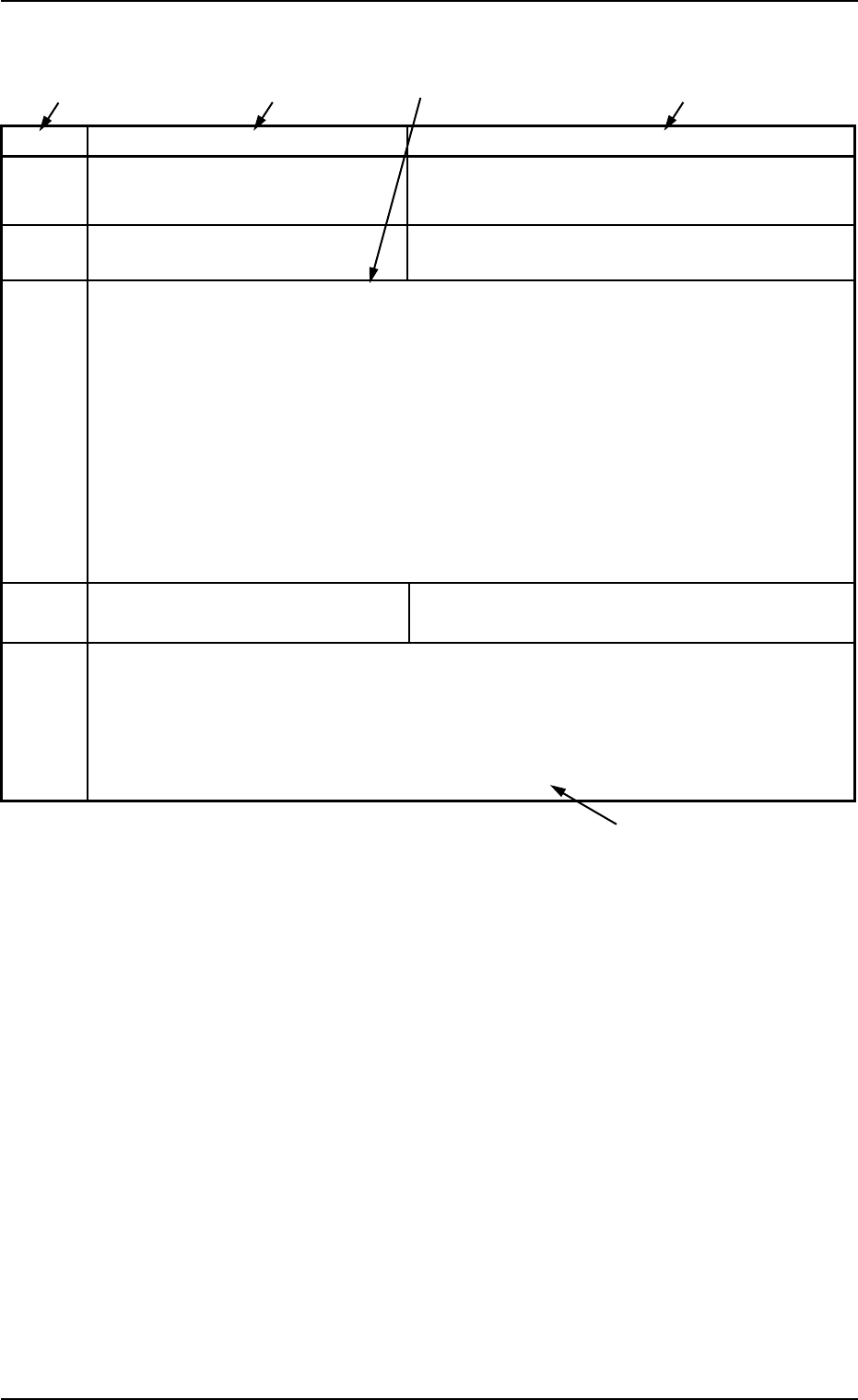
3.1 Typical Description
Table 4B4
Error ID Item Description
11040* L CONVEYOR WIDTH LIMIT (+) LIMIT ERROR HAS BEEN DETECTED.
; BPH77 E/NR
11040* L CONVEYOR WIDTH LIMIT (-) LIMIT ERROR HAS BEEN DETECTED.
; BPH77 E/NR
(Cause 1) An optical beam of the sensor is shielded.
(Cause 2) Dirt adheres to the sensor and the optical beam is shielded.
(Cause 3) The sensor is defective.
(Remedy 1) Turn off the power supply and move the conveyor width with the manual knob for
easier operation. Re-attach the light shield plate or the sensor securely (remove
the looseness).
(Remedy 2) Wipe off dirt on the sensor and zero the L conveyor again.
(Remedy 3) Replace the sensor with a new one.
12010* R CONVEYOR WIDTH ORIGIN OUTPUT SIGNAL FROM THE PULSE MOTOR DRIVER
WAS NOT DETECTED.
(Cause 1)
(Remedy 1)
(Continued to the next page)
*1 The error IDs (IDs displayed in the “ERROR” window) are described
in the numerical order.
“*” in the table will be filled with a numeric character.
*2 Described are the error name (item) and the description in the “ER-
ROR” window.
*3 Described are the causes and remedial procedures of the errors
in “*2 (Item and Description)”.
The causes and remedies are correlated as follows.
(Cause 1)
ÆÆ
ÆÆ
Æ (Remedy 1)
(Cause 2)
ÆÆ
ÆÆ
Æ (Remedy 2)
(Cause 3)
ÆÆ
ÆÆ
Æ (Remedy 3)
*4 This indicates that the related contents are described subsequently
on the next page.
0307-005 2-31 AFO01ETRP
*4
*2
*3
*2
*1
3.1 Typical Description
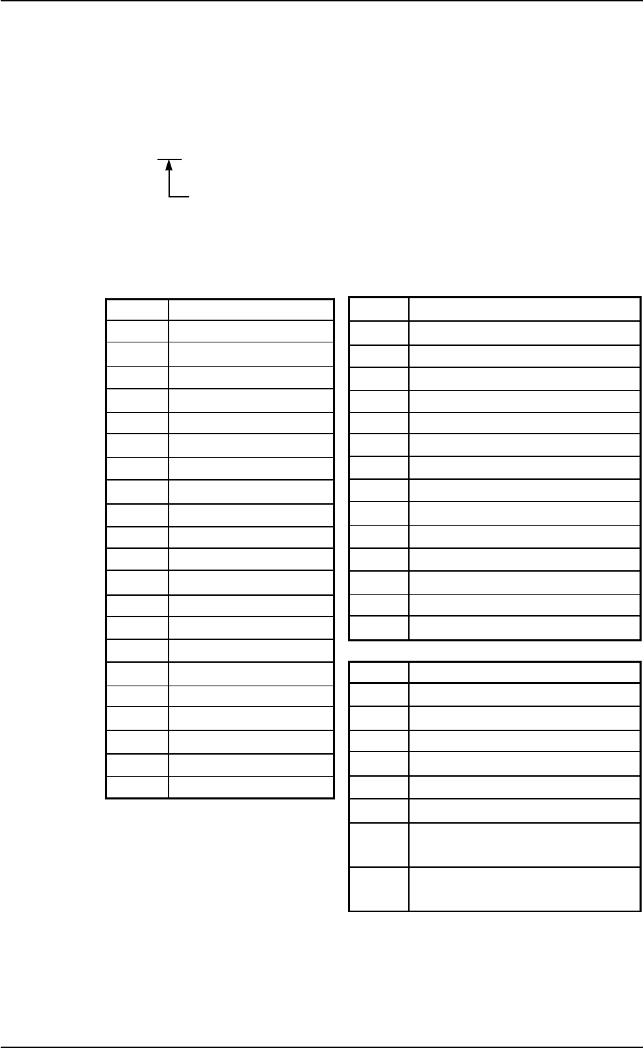
3.2 Error IDs and Controlled Areas
Basic System of Error IDs
An error ID is expressed by 6 digits (hexadecimal) as follows.
Major Classification of “Operation Axis”, “Process Error”,
and “Teaching Operation”
Error IDs and Controlled Areas
Table 4B5
Error ID Operation Axis Error ID Process Error
02 Rotary Turret 40 Safety Device
03
Component Pickup (Z) Axis 41 Data
04
Component Placement (Z) Axis 42 Conveyor
05 Table X 43 Self-Diagnostics 1
06 Table Y 44 Self-Diagnostics 2
07 X/Y Conveyor 45 Recognition Communication
08 Feeder Carriage #1 46 P.E.C. Recognition
09 Feeder Carriage #2 47 Pickup Error
0a Feeder Carriage #3 48 Component Recognition
0b Feeder Carriage #4 49 Control P.C.B.
0c Head 4a Camera Teaching/Correction
0d Camera X 4b Others
0e Camera Y 4c Unit P.C.B. B.B.R. Mode
0f P.C.B. Transfer 4f Program Error
10 X/Y Chute Width
11 L Conveyor Width Error ID Teaching Operation
12 R Conveyor Width 60 Nozzle Position
13 Support Pin U/D 61
Lighting for Component Recognition
14 P.C.B. Locate Lever 62 Nozzle Level
15 L2 Conveyor 63
Head Center Offset/Nozzle Position
16 R2 Conveyor 64 Master Head Offset
65 Head Origin Offset
66 Teaching (Dust/Dirt Detection (Cam-
era))
67 Teaching (Dust/Dirt Detection
(Diffusion Plate/Nozzle))
0301-004 2-32 AFO01ETRP
3.2 Error IDs and Controlled Areas

3.3 Error IDs and Remedial Procedures
Table 4B6
Error ID Item Description
020101 Rotary Turret Origin Rotary turret angle is not at origin.
020102 Rotary Turret Origin Rotary turret angle is not at the proper position.
020103 Rotary Turret Origin Placement heads can not be controlled properly.
020104 Rotary Turret Origin Rotary turret is not at origin.
(Cause 1) Self-Diagnostics Error Message
(Remedy 1) Zero all axes and re-start the operation.
When the machine cannot be set to its normal condition, consult our service
personnel for the remedy.
020201 Rotary Turret Timing Task has not been completed unable to continue.
020202 Rotary Turret Timing Task has not been completed during allowed time.
(Cause 1) Self-Diagnostics Error Message
(Remedy 1) Zero all axes and re-start the operation.
When the machine cannot be set to its normal condition, consult our service
personnel for the remedy.
020301 Rotary Turret Data The driver data was detected outside of the possible range.
(Cause 1) Self-Diagnostics Error Message
(Remedy 1) Zero all axes and re-start the operation.
When the machine cannot be set to its normal condition, consult our service
personnel for the remedy.
020502 Rotary Turret Servo Alarm User constant breakdown. [Shutdown touch sw key and
mainbreaker sw off.]
020503 Rotary Turret Servo Alarm Main circuit encoder error
020504 Rotary Turret Servo Alarm User constant setting error. [Shutdown touch sw key
and mainbreaker sw off.]
020505 Rotary Turret Servo Alarm Combination error
(Cause 1) Self-Diagnostics Error Message
(Remedy 1) Zero all axes and re-start the operation.
When the machine cannot be set to its normal condition, consult our service
personnel for the remedy.
0110-003 2-3 3 AFO01ETRP
3.3 Error IDs and Remedial Procedures