4OM-1050-002.pdf - 第224页
Error ID Item Description 430301 Head No. The head no. Detection sensor was not activated. (Cause 1) Self-Diagnostics Error Message (Remedy 1) Zero all axes and re-start the operation. When the machine cannot be set to i…

Error ID Item Description
430203 NOZZLE POSITION THE SELECTED NOZZLE LEVEL WAS NOT AT HIGH PO-
SITION.; BPH16
430204 NOZZLE POSITION THE SELECTED NOZZLE LEVEL WAS NOT AT LOW
POSION.; BPH16
(Cause 1) The optical beam was not set in the “E/R” or the “E/NR” condition due to dirt on the
sensor. (E/R: Light Emitted and Received, E/NR: Light Emitted and Not Received).
The sensor may be defective.
(Remedy 1) Confirm that no dirt adheres to the sensor. Or, it may be necessary to replace the
sensor with a new one because it may be defective.
Before replacing the sensor, contact our service personnel for some advice.
430205 NOZZLE POSITION THE SELECTED NOZZLE LEVEL POSITION SENSOR WAS
NOT ACTIVATED.; BPH15, 16
(Cause 1) The optical beam was not set in the “E/R” or the “E/NR” condition due to dirt on the
sensor. (E/R: Light Emitted and Received, E/NR: Light Emitted and Not Received).
The sensor may be defective.
(Remedy 1) Press the [RETURN] button to cancel the error display and check that no dirt
adheres to the sensor.
430206 NOZZLE POSITION THE UNSELECTED NOZZLE WAS ERRONEOUSLY POSI-
TIONED.; BPH17, BPH18
(Cause 1) The optical beam was not set in the “E/R” or the “E/NR” condition due to dirt on the
sensor. (E/R: Light Emitted and Received, E/NR: Light Emitted and Not Received).
The sensor may be defective.
(Cause 2) This error occurs when the nozzle almost comes off at Station #8 and touches the
component discharge plate.
(This error occurs during automatic or manual operation.)
(Remedy 1) Confirm that no dirt adheres to the sensor. Or, it may be necessary to replace the
sensor with a new one because it may be defective.
Before replacing the sensor, contact our service personnel for some advice.
(Remedy 2) Check the head at Station #8. Subsequently, perform the reverse rotation opera-
tion to move the head back toward the front side of the machine. Then, insert the
nozzle deep inside.
0110-003 2-106 AFO01ETRP
3.3 Error IDs and Remedial Procedures

Error ID Item Description
430301 Head No. The head no. Detection sensor was not activated.
(Cause 1) Self-Diagnostics Error Message
(Remedy 1) Zero all axes and re-start the operation.
When the machine cannot be set to its normal condition, consult our service
personnel for the remedy.
430401 X/Y Table P.C.B. was dislodged while the X/Y table was in motion.
430402 X/Y Table P.C.B. was dislodged while the X/Y table was in motion.
(Cause 1) The P.C.B. is trapped on the X/Y table.
The P.C.B. pilot pin, the positioning lever, and the P.C.B. support pin are not located
at their regular positions.
(Remedy 1) Check how the P.C.B. pilot pin, the positioning lever, and the P.C.B. support pins
are attached.
430403 X/Y Table X/Y chute has gone up while X/Y table was in motion.
(Cause 1) Self-Diagnostics Error Message
(Remedy 1) Zero all axes and re-start the operation.
When the machine cannot be set to its normal condition, consult our service
personnel for the remedy.
0110-003 2-107 AFO01ETRP
3.3 Error IDs and Remedial Procedures
Error ID Item Description
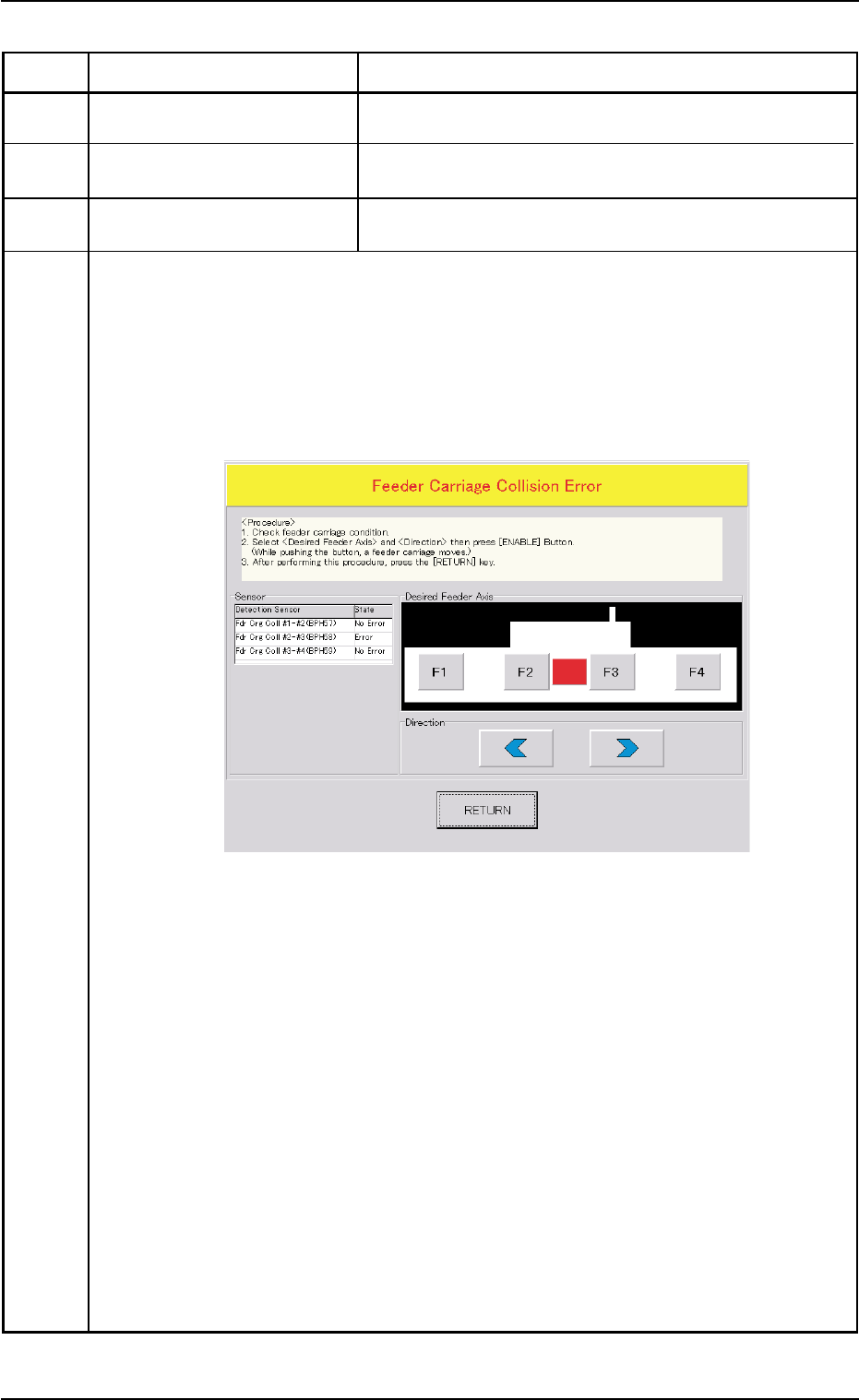
430501 Feeder Carriage Fdr.crg. axis motor #1 & #2 have collided.
430502 Feeder Carriage Fdr.crg. axis motor #2 & #3 have collided.
430503 Feeder Carriage Fdr.crg. axis motor #3 & #4 have collided.
(Cause 1) Dirt adheres to the sensor and the optical beam of the sensor is shielded.
(Cause 2) The sensor position may be wrong or the sensor may be defective.
The servo pack may be defective.
(Remedy 1) When the [RETURN] button is pressed, the "Feeder Carriage Collision Error"
window opens.
Follow the instructions described in this window and the procedure below for the
reset operation.
Notes: (a) When the power is re-supplied without following the correct procedure
to cancel the error, the feeder carriage collision error will be detected
again and the message will be issued because the contents of the
feeder carriage collision error are backed up.
(b) No zeroing operation can be performed when a feeder carriage collision
error is not canceled completely.
(1) Confirm that there is no error in the feeder carriage section.
(2) Select the object feeder and the direction of the movement. After that, press
the [ENABLE] button to move the feeder carriages in separate directions.
Note: While the [ENABLE] button is held down, the feeder carriages keep on
moving.
(3) After Step (2), press the [RETURN] button.
Ref.: The original window resumes.
(4) Zero all axes and re-start the operation.
(Remedy 2) Contact our service personnel for details.
0110-003 2-108 AFO01ETRP
Fig. 4B17
3.3 Error IDs and Remedial Procedures