YSM40_mpl.pdf - 第4页
Contents KLF1304 Nozzle Changer (Base) ............................. 6-3 Nozzle Changer (HS) ................................ 6-4 7 Conveyor Section Push-Up A / C ........................................... 7-1 Push-Up B…
Note
Rank A : The functions of these parts gradually deteriorate with operating time.
Rank B : The machine stops immediately if the functions of these parts are disabled.
Rank C : The machine still operates even if the functions of these parts are disabled,
because there are many parts.
Rank E : The functions of consumable part gradually deteriorate with operating time.
/ : Maintenance is excluded (The screws are also equal, display is omitted)
Level
: Aims to undergo basic maintenance training and have the capability to do the
job.
Level
r
: Yamaha Corp. aims to render exclusive training
Level
Í
: Yamaha Corp. Service Engineering
Rev.
: It had a change without the compatibility. Please be careful at the time of the
parts ordering.
Level column
Make use of these as reference, “
•
r
•×”, as mentioned in the Level column.
“
” It is based on taking the basic maintenance training, and being able to do
equal work.
“
” Please contact our company service when it is judged that the customer’s
condition difcult.
From the problem that arises from these, we cannot assume responsibility such as
accidents.
NOTE
RankA: 機能が徐々に失われる可能性のある部品。
RankB: 機能を失うとマシンの即停止に繋がる部品。
RankC: 機能を失っても複数あるのでマシンの即停止とはならない部品。
RankE: 機能が徐々に失われていく消耗部品。
/ :メンテナンス対象外(ネジ類も同等、但し表示省略)
Level
: 基礎メンテナンストレーニングを受けた方、又は同等の作業ができる方が対象。
Level
r
: ヤマハの専用トレーニングを受けた方が対象です。
Level
Í
: ヤマハのサービスマンが対象です。
Rev.
:過去に互換性の無い変更が入った部品。部品発注時は注意してください。
Level 欄について
Level 欄に記載されている
“
•
r
•×”
はご参考としてご活用ください。
“
”
は基礎メンテナンストレーニングを受けた方、又は同等の作業ができる方を
基準にしております。
“
”
であってもお客様が難しいとご判断された時は弊社サービスまでご連絡ください。
これらに起因する不具合、事故等についての責任は負いかねます。

Contents
KLF1304
Nozzle Changer (Base) .............................6-3
Nozzle Changer (HS) ................................6-4
7 Conveyor Section
Push-Up A / C ...........................................7-1
Push-Up B / D ...........................................7-2
Trasport .....................................................7-3
DL Sensor .................................................7-4
Frame Assy ...............................................7-5
Clamp Board Sub Assy 1 ..........................7-6
Clamp Board Sub Assy 2 .........................7-7
Pin Sensor ................................................7-8
Extension ..................................................7-9
8 Blow Station Section
Blow Station ..............................................8-1
9 FDR Section
Set Up ST on MC ......................................9-1
FDR Power ST ..........................................9-2
FDR Stand Type144 .................................9-3
Dust Box ...................................................9-4
10 Controller Section
Controller ................................................10-1
11 Exterior, etc. Section
Exterior, etc. ............................................ 11-1
12 Tools Section
Tools ........................................................12-1
1 Base Section
Base ..........................................................1-1
Sub Assy / UPS ......................................... 1-2
2 Cover Section
Door / USB-Box. .......................................2-1
Base ..........................................................2-2
3 Feeder Holder Section
Bank FES46 Rail Guide ............................3-1
Cover FES46 Moveig Part ........................ 3-2
Cover FES46 Base / Sensor .....................3-3
Reel Holder ...............................................3-4
Carriage FES46 ........................................3-5
4 Moving-axis Section
X-axis Motor / Sensor / Cover (4-Beam) ...4-1
Y-axis Sensor / Cable (2/4 Beam) .............4-2
X-axis Motor / BS (2-Beam) ......................4-3
5 Head Section
Head(MU) .................................................5-1
Head Shaft Assy(MU) ...............................5-2
Head (FL) ..................................................5-3
Nozzle Holder (FL) ....................................5-4
Rotary Shaft Assy (HS) .............................5-5
Flow Sensor / S.V.Camera(HS) ................ 5-6
6 Nozzle Section
Nozzle .......................................................6-1
Nozzle Changer (MU/FL Holder) ..............6-2
KLF-1309
22
1
34
34
3
3
2
2
3
3
2
2
24
31
4
4
25
24
31
25
31
7
27
27
27
27
29
10
10
41
42
39
25
31
31
13
18
44
45
35
36
19
46
23
26
16
28
15
37
21
20
25
38
32
14
28
23
9
8
7
33
6
33
26
26
22
22
30
12
30
5
5
1
43
11
17
47
1
1
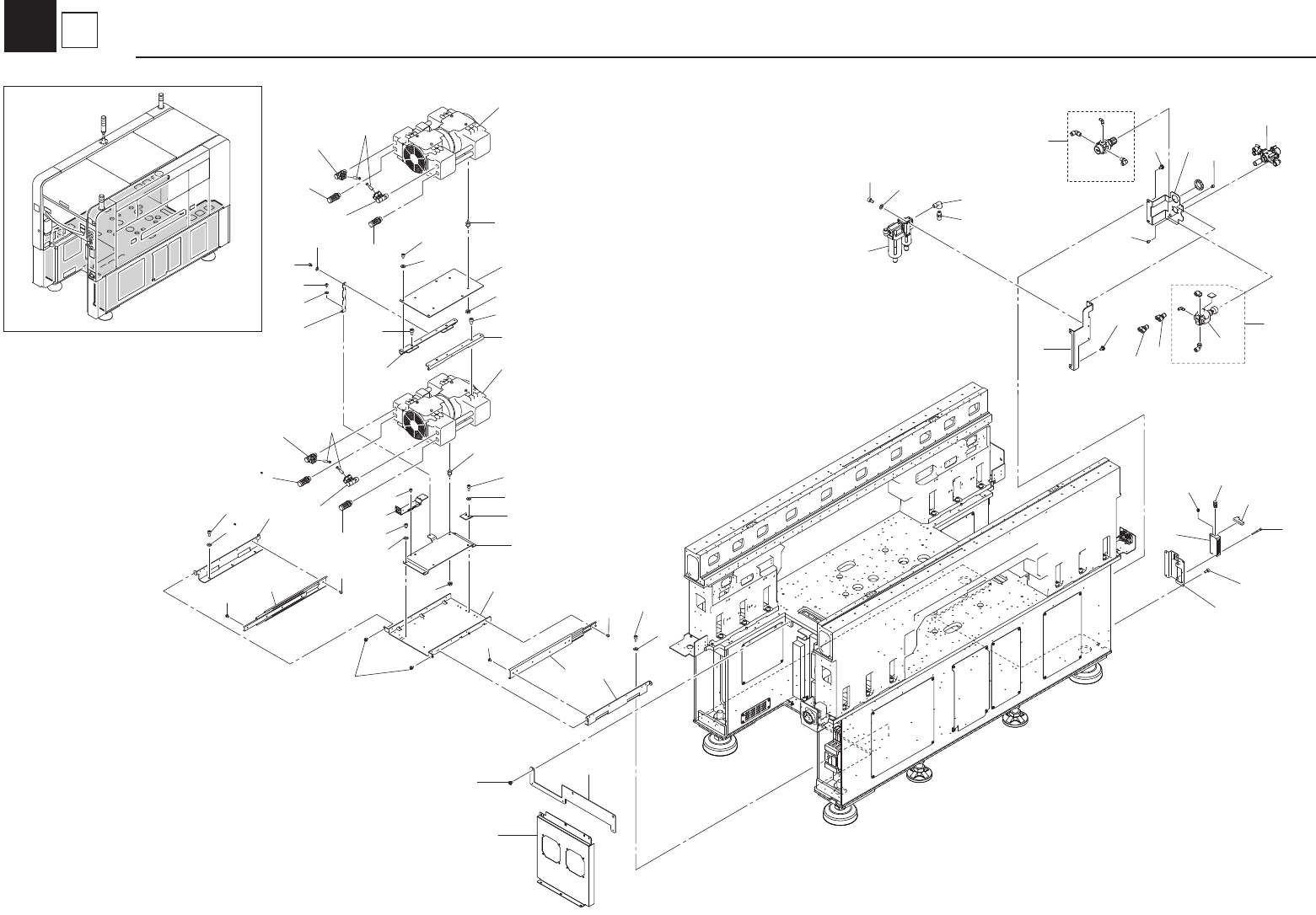
Base
Base