00193437-03_AI_PowerSupplyConversion_DE+EN.pdf - 第152页
2 Safety check to DIN EN 60 204 Assembly Instructions, Converting the Power Supply 2.4 High-voltage test 12/2013 Edition 150 WA R N I N G 2 Parts of the system that a re not rated for the test voltage must be disconnecte…
Assembly Instructions, Converting the Power Supply 2 Safety check to DIN EN 60 204
12/2013 Edition 2.4 High-voltage test
149
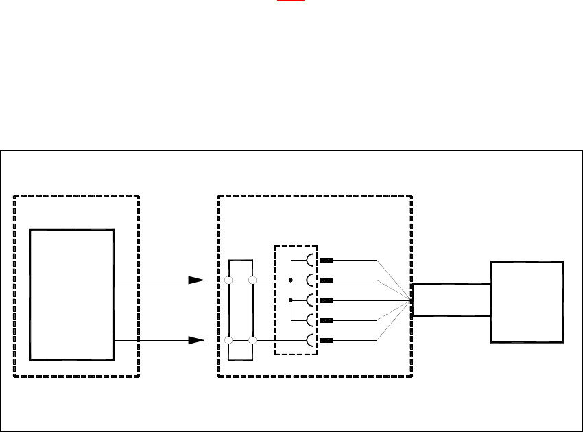
2.3.3 Performing the insulation test
Create a test set-up as illustrated in figure 2 - 3.
Follow the instructions in the manual for the testing device.
Measure the insulation resistance at 500 VDC.
Enter the measured value into the test report.
If the measured value is > 1.0 MOhm, the machine has passed the insulation test and can be
released. If the measured value is smaller, the error must be eliminated and the test repeated.
Fig. 2 - 3 Insulation test set-up
2.4 High-voltage test
2.4.1 Minimum durations and voltages for the high-voltage test
The electrical system must withstand a test voltage applied between the conductors of all the
power circuits and the PE conductor system for at least 10 seconds. 2
The test voltage must 2
– be twice the rated voltage for the electrical system or 1000 VAC (Canada: 1500 VAC), which-
ever is the higher.
– have a frequency of 50/60 Hz and
– be powered by a transformer with a minimum rated output of 500 VA.
2
PE
N
L3
L2
L1
L1
L2
L3
N
PE
METRAWATT
tester
METRAWATT 204P, METRAMACHINE 204
grounding socket
three-phase current plug or
Distributor box with
Power cable
Probe tips
Machine,
WPC
CO table,
supply for
Power
2 Safety check to DIN EN 60 204 Assembly Instructions, Converting the Power Supply
2.4 High-voltage test 12/2013 Edition
150
WARNING 2
Parts of the system that are not rated for the test voltage must be disconnected. This particularly
applies to the monitor. 2
2.4.2 High-voltage testers
2
2.4.3 Performing the high-voltage test
– Disconnect the monitor.
– In the distributor box, connect the three-phase AC socket or socket with earthing contact to the
power cable for the machine, component table or MTC/MTC2. The test set-up is shown in fig-
ure 2 - 3
.
RISK OF DEATH 2
To protect the test set-up, you will need 2
a barrier chain
a red flashing light to signal the high-voltage tests and keep unauthorized personnel away from
the system.
Switch on the testing device and measure the equivalent leakage current with the following set-
tings:
- 1000 VAC (Canada 1500 VAC)
- Test duration 10 sec.
Measure the equivalent leakage current (active or apparent current).
Available testers
– GOSSEN-METRAWATT 204P
– METRAMACHINE 204/2,5 (complete system for tests to EN 60204-1
(VDE0113) consisting of Profitest 204, Profitest 204 HP, Signal 204,
Leadex 204, and Caddy 204
Power output 500 VA
Test duration 10 seconds
Tab. 2 - 2 High-voltage testers
Assembly Instructions, Converting the Power Supply 2 Safety check to DIN EN 60 204
12/2013 Edition 2.5 PE conductor test
151
2.5 PE conductor test
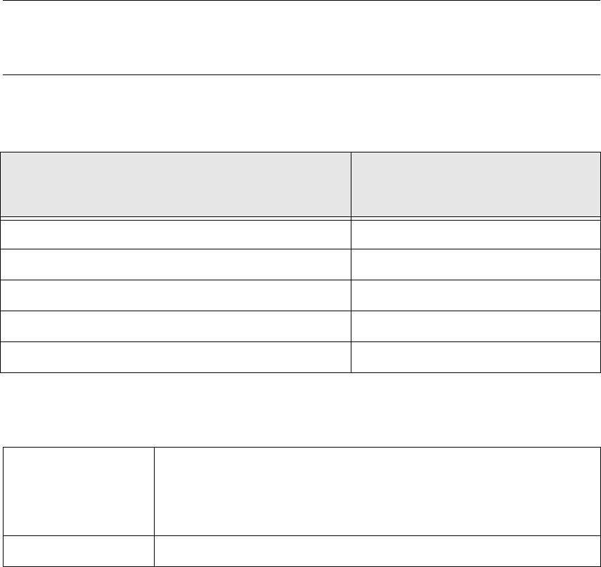
2.5.1 Permissible impedance values for the PE conductors
The PE test is used to test the continuity of the PE conductor system by means of a loop imped-
ance measurement to IEC 60364-6-61, 612.6.3. 2
PLEASE NOTE:
All the electrical connections must be fully installed on the machine, including those for the power
supply. 2
The impedances measured between the PE terminal and the test points must not exceed the val-
ues shown in the following table. 2
2.5.2 PE conductor testers
Smallest effective PE conductor cross-section in
branch to be tested
[mm²]
Maximum permissible impedance
[Ohm]
1.0 0.33
1.5 0.26
2.5 0.19
4.0 0.14
> 6.0 0.1
Tab. 2 - 3 Permissible impedance values for different PE conductor cross-sections
Available testers
– GOSSEN-METRAWATT 204P
– METRAMACHINE 204/2,5 (complete system for tests to EN 60204-1
(0113VDE 0113) consisting of Profitest 204, Profitest 204 HP, Signal 204,
Leadex 204, Caddy 204
Test duration 10 seconds
Tab. 2 - 4 PE conductor testers