00193437-03_AI_PowerSupplyConversion_DE+EN.pdf - 第183页
Assembly Instructions, Converting the Power S upp ly 4 Converting the power supply o n the MTC2 12/2013 Edition 4.3 Modules to be converted 181 4.3 Modules to be co nverted The following table lists those modules that ha…

4 Converting the power supply on the MTC2 Assembly Instructions, Converting the Power Supply
4.1 Tools and equipment 12/2013 Edition
180
4 Converting the power supply on the MTC2
This section describes how to convert the power supply unit for the matrix tray changer 2 (MTC2)
on the HF placement machine in order to adapt it to the supply networks in individual countries.4
PLEASE NOTE: 4
The conversion can only be carried out if the MTC2 was supplied with the "USA conversion kit for
MTC2" option (item no. 00116437-01). 4
4.1 Tools and equipment
– Set of DIN 911 Allen keys
– Set of slotted-head screwdrivers
– Multimeter
4.2 Parts
The following parts are supplied with the accessory bag: 4
– Jumper, gray, 3 x
item no. 00353338-01
Assembly Instructions, Converting the Power Supply 4 Converting the power supply on the MTC2
12/2013 Edition 4.3 Modules to be converted
181
4.3 Modules to be converted
The following table lists those modules that have to be converted in order to adapt them to the
power supply network.
4.4 Converting the power supply from 3 x 400 VAC to 3 x 208 VAC
Dock the MTC2 out of the placement machine.
RISK OF DEATH 4
Disconnect the MTC2 from the main power supply.
Take suitable action to ensure that the MTC2 cannot be connected to the power supply during
the conversion work.
Put up warning signs to indicate that work is being carried out on the electrical system.
Module Sub-module Ratings
Electronic panel Terminal panel X01
3 x 400 VAC ± 5%
3 x 208 VAC ± 5%
50 - 60 Hz
Tab. 4 - 1 Modules to be converted
4 Converting the power supply on the MTC2 Assembly Instructions, Converting the Power Supply
4.4 Converting the power supply from 3 x 400 VAC to 3 x 208 VAC 12/2013 Edition
182
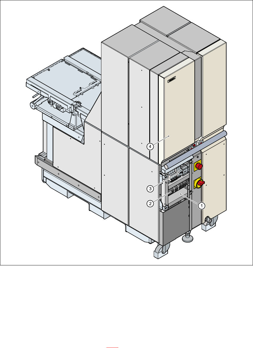
4.4.1 Conversion work on the electronic panel
4
Fig. 4 - 1 Position of the electronic panel for the MTC2
(1) Electronic panel
(2) Terminal block X01
(3) Motor contactor Q01
(4) Door, left-hand side
4
Open the left door (see item 4 in Fig. 4 - 1).
Release the screws for the electronic panel cover.