00193437-03_AI_PowerSupplyConversion_DE+EN.pdf - 第184页
4 Converting the power supply on the MTC2 Asse mbly Instructions, Converting the Power Supply 4.4 Converting the power supply from 3 x 400 VAC to 3 x 208 VAC 12/2013 Edition 182 4.4.1 Conversion work on the electronic p …
Assembly Instructions, Converting the Power Supply 4 Converting the power supply on the MTC2
12/2013 Edition 4.3 Modules to be converted
181
4.3 Modules to be converted
The following table lists those modules that have to be converted in order to adapt them to the
power supply network.
4.4 Converting the power supply from 3 x 400 VAC to 3 x 208 VAC
Dock the MTC2 out of the placement machine.
RISK OF DEATH 4
Disconnect the MTC2 from the main power supply.
Take suitable action to ensure that the MTC2 cannot be connected to the power supply during
the conversion work.
Put up warning signs to indicate that work is being carried out on the electrical system.
Module Sub-module Ratings
Electronic panel Terminal panel X01
3 x 400 VAC ± 5%
3 x 208 VAC ± 5%
50 - 60 Hz
Tab. 4 - 1 Modules to be converted
4 Converting the power supply on the MTC2 Assembly Instructions, Converting the Power Supply
4.4 Converting the power supply from 3 x 400 VAC to 3 x 208 VAC 12/2013 Edition
182
4.4.1 Conversion work on the electronic panel
4
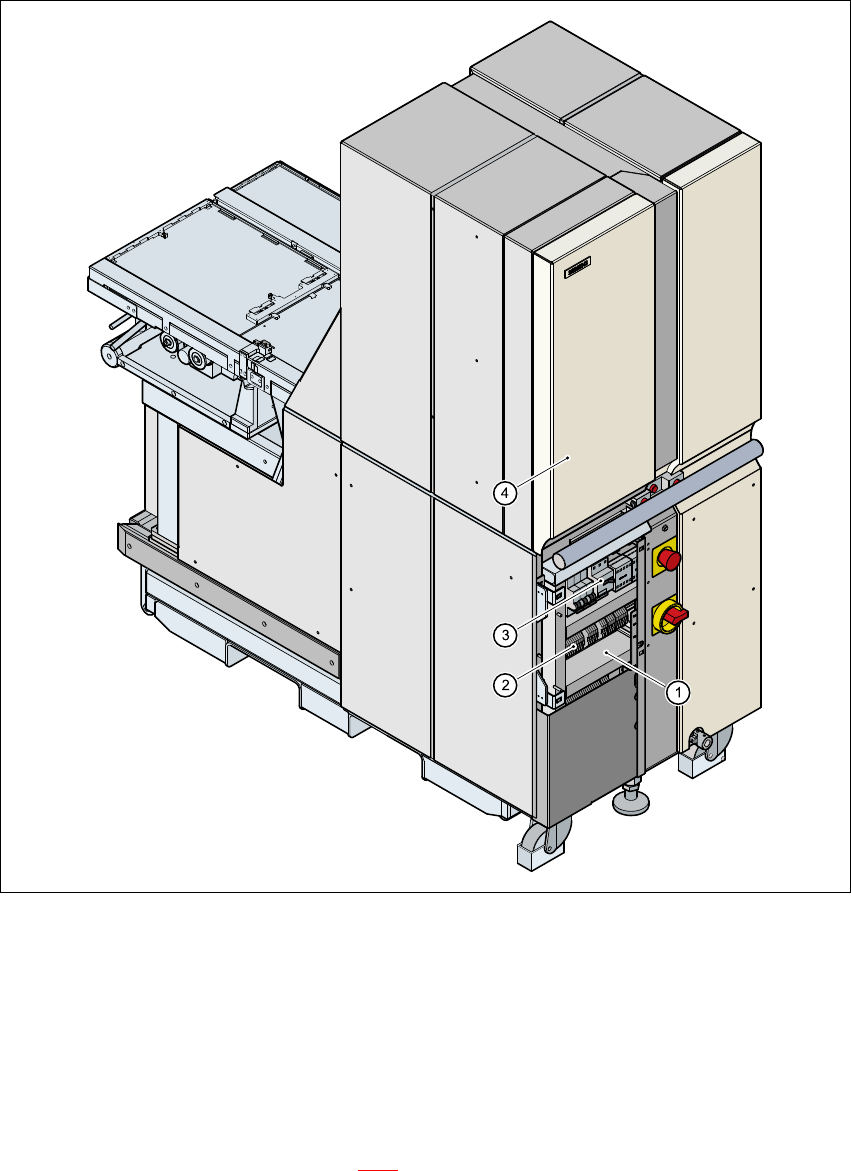
Fig. 4 - 1 Position of the electronic panel for the MTC2
(1) Electronic panel
(2) Terminal block X01
(3) Motor contactor Q01
(4) Door, left-hand side
4
Open the left door (see item 4 in Fig. 4 - 1).
Release the screws for the electronic panel cover.
Assembly Instructions, Converting the Power Supply 4 Converting the power supply on the MTC2
12/2013 Edition 4.4 Converting the power supply from 3 x 400 VAC to 3 x 208 VAC
183
Lift off the cover.
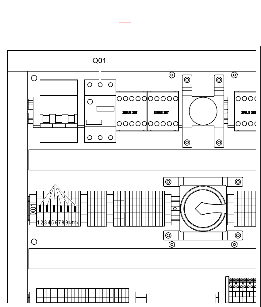
Remove the three transverse jumpers from feed-through terminals 2-3, 6-7 and 10-11 on ter-
minal block X01 (point 2 in Fig. 4 - 1
).
On terminal block X01, plug in six transverse jumpers between feed-through terminals 1-2, 3-
4, 5-6, 7-8, 9-10 and 11-12 (BR see Fig. 4 - 2
).
Leave the tripping current setting unchanged at 3.5 A on motor contactor Q01.
4
Fig. 4 - 2 MTC2 electronic panel - jumper set for 3 x 208 VAC
JMP jumper, 6 x 4
Q01 motor contactor 4
X01 terminal block 4
JMP (3 x 208 VAC) 4