00193437-03_AI_PowerSupplyConversion_DE+EN.pdf - 第196页
5 Converting the power supply on S-27 HM machines/ and on component trolleys Assembly Instructions, Converting the Power Supply 5.6 Converting the S-27 HM from 3 x 400 VAC to 3 x 208 VAC 12/2013 Edition 194 Fig. 5 - 2 Ca…
Assembly Instructions, Converting the Power Supply 5 Converting the power supply on S-27 HM machines/ and on component trolleys
12/2013 Edition 5.6 Converting the S-27 HM from 3 x 400 VAC to 3 x 208 VAC
193
5.6.1 Removing the power supply unit
Loosen the two hexagon socket head screws (item 2 in Fig. 5 - 1).
Remove the cover (item 3 in Fig. 5 - 1).
Loosen the hexagon socket-head screw at the bottom of the power supply unit.
Take hold of the handle and remove the power supply unit from the housing.
The terminals on transformers T1 and T2 and the inrush current limiter can now be accessed
for rewiring.
5
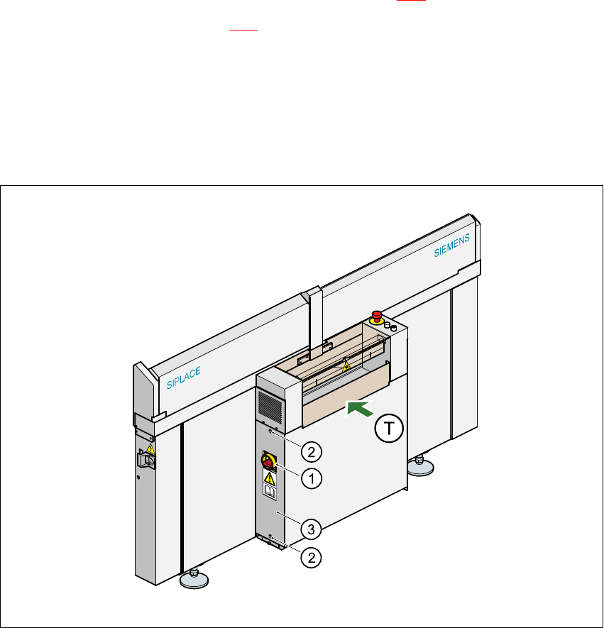
Fig. 5 - 1 Removing the cover over the power supply unit
5
(1) Main switch
(2) Hexagon socket head screw, 2x
(3) Cover
(T) PCB transport direction 5
5 Converting the power supply on S-27 HM machines/ and on component trolleys Assembly Instructions, Converting the Power Supply
5.6 Converting the S-27 HM from 3 x 400 VAC to 3 x 208 VAC 12/2013 Edition
194
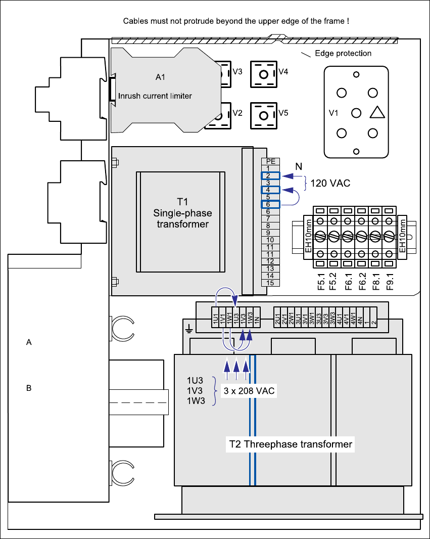
Fig. 5 - 2 Cable connection terminals for the transformers T1 and T2 and the inrush current limiter (3 x 208 VAC)
(T1) Single-phase transformer T1 2 - 6 230 VAC
2 - 4 120 VAC
(T2) Three-phase transformer T2 1U1, 1V1, 1W1 3 x 400 VAC
1U3, 1V3, 1W3 3 x 208 VAC
(A1) Inrush current limiter 5

Assembly Instructions, Converting the Power Supply 5 Converting the power supply on S-27 HM machines/ and on component trolleys
12/2013 Edition 5.6 Converting the S-27 HM from 3 x 400 VAC to 3 x 208 VAC
195
5.6.2 Converting the single-phase transformer T1 from 230 VAC to 120 VAC
Detach the black connecting wire from terminal (6) (230 VAC) and connect to terminal (4)
(120 VAC) (see Fig. 5 - 2
).
5.6.3 Converting the three-phase transformer T2 from 3 x 400 VAC to 3 x 208 VAC
Detach the black connecting wire from terminal 1 U1 (400 VAC) and connect to terminal 1U3
(208 VAC) (see Fig. 5 - 2
).
Detach the black connecting wire from terminal 1 V1 (400 VAC) and connect to terminal 1V3
(208 VAC) (see Fig. 5 - 2
).
Detach the black connecting wire from terminal 1 W1 (400 VAC) and connect to terminal 1W3
(208 VAC) (see Fig. 5 - 2
).
5.6.4 Converting the inrush current limiter A1 from 3 x 400 VAC to 3 x 208 VAC
Detach wire (3) from terminal 13 and connect to terminal 14 (see Fig. 5 - 3).
Detach wire (6) from terminal 23 and connect to terminal 24 (see Fig. 5 - 3).
Detach wire (9) from terminal 33 and connect to terminal 34 (see Fig. 5 - 3).
Detach wire (2) from terminal 12 and connect to terminal 13 (see Fig. 5 - 3).
Detach wire (5) from terminal 22 and connect to terminal 23 (see Fig. 5 - 3).
Detach wire (8) from terminal 32 and connect to terminal 33 (see Fig. 5 - 3).
5.6.5 Installing the power supply unit
Carefully push the power supply unit into the housing until it reaches the stop.
Use the hexagon socket-head screw to secure the unit at the bottom.
Check that the yellow-green PE wire is connected to the cover.
Replace the cover.
PLEASE NOTE: 5
Make sure that the actuating shaft of the main switch slides easily into the opening in the ro-
tary button. 5
Fix the cover in place using the two hexagon socket head screws.