00193437-03_AI_PowerSupplyConversion_DE+EN.pdf - 第200页
5 Converting the power supply on S-27 HM machines/ and on component trolleys Assembly Instructions, Converting the Power Supply 5.6 Converting the S-27 HM from 3 x 400 VAC to 3 x 208 VAC 12/2013 Edition 198 5.6.6.2 4-wir…
Assembly Instructions, Converting the Power Supply 5 Converting the power supply on S-27 HM machines/ and on component trolleys
12/2013 Edition 5.6 Converting the S-27 HM from 3 x 400 VAC to 3 x 208 VAC
197
5.6.6 5 or 4-wire connection for the power supply
The connections are produced using either 5 or 4 wires, according to the electricity company's re-
quirements. The placement machine is supplied with a 5-wire connection as standard. 5
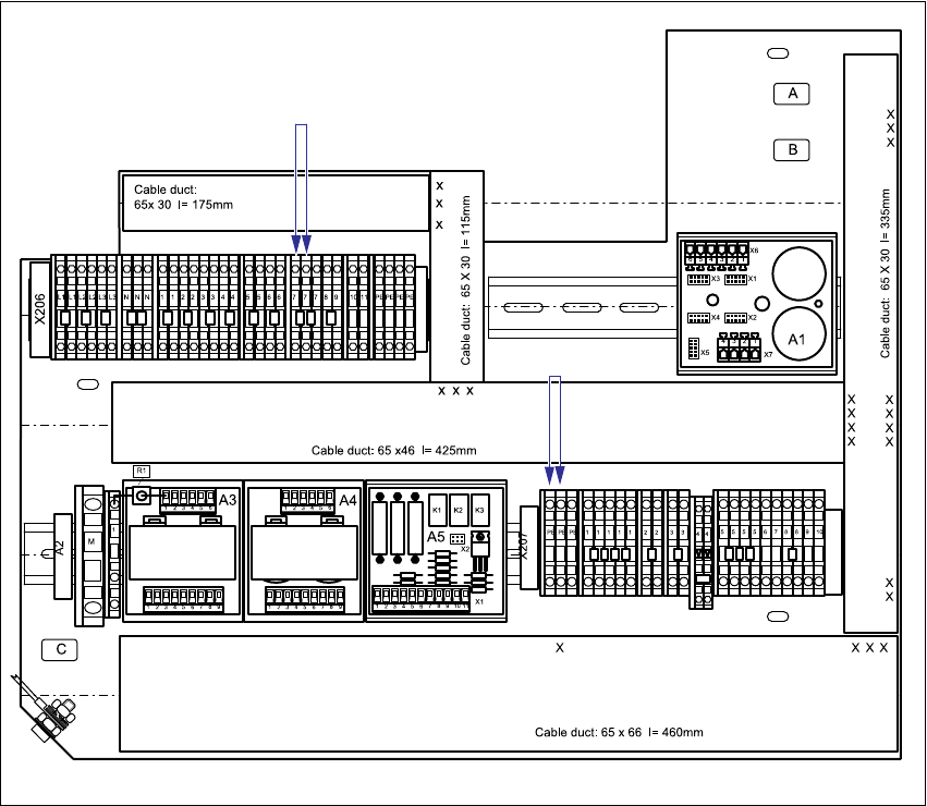
5.6.6.1 5-wire connection
In the 5-wire connection, the neutral conductor (NE) and protective earth (PE) consist of separate
wires. 5
Two additional yellow-green jumper cables BR1 and BR2 are connected to terminal strips
X206:PE and X207:7 in the "Voltages" terminal panel. These jumper cables are then recon-
nected for a 4-wire connection.
Fig. 5 - 4 Terminal panel "Voltages", 5-wire connection
JMP1 (yegn) 5
JMP2 (yegn) 5
5 Converting the power supply on S-27 HM machines/ and on component trolleys Assembly Instructions, Converting the Power Supply
5.6 Converting the S-27 HM from 3 x 400 VAC to 3 x 208 VAC 12/2013 Edition
198
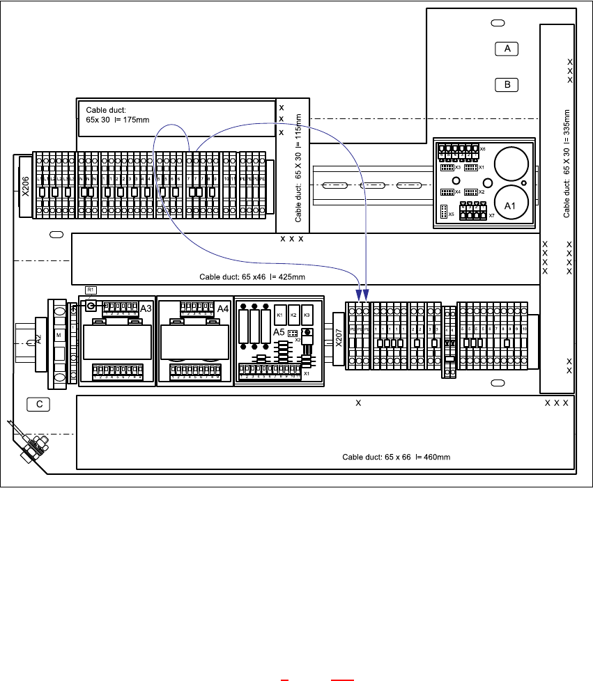
5.6.6.2 4-wire connection
In the 4-wire connection, the neutral conductor (NE) and protective earth (PE) are combined to
form a single PEN wire. The two jumper cables BR1 and BR2 are connected in order to create a
4-wire connection: 5
JMP1 connects X206:7 to X207:PE
JMP2 connects X206:7 to X207:PE 5
Fig. 5 - 5 Terminal panel "Voltages", 4-wire connection
5.6.7 Insert the socket guard into the X1 service socket.
For the USA version, insert the socket guard into the X1 service socket.
5.6.8 Carry out the safety check to DIN EN 60 204
When the conversion is complete, carry out a safety check to DIN EN 60 204.
Follow the procedure described in section 2, page 146 onwards.
JMP1 (yegn) 5 JMP2 (yegn) 5
Assembly Instructions, Converting the Power Supply 5 Converting the power supply on S-27 HM machines/ and on component trolleys
12/2013 Edition 5.7 Converting the component trolley from 230 VAC to 120 VAC
199
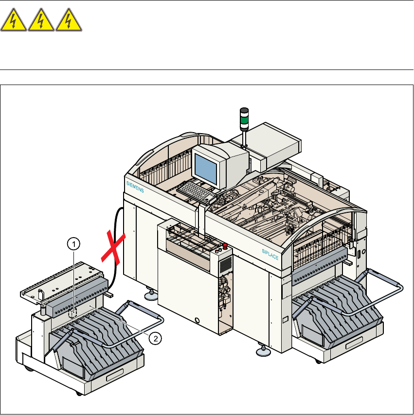
5.7 Converting the component trolley from 230 VAC to 120 VAC
RISK OF DEATH 5
The component trolley must be docked out during the rewiring work. The power cable and com-
munication cable must both be unplugged. 5
Fig. 5 - 6 Component trolley, transformer T1
(1) Transformer T1
(2) Top part of frame