00193437-03_AI_PowerSupplyConversion_DE+EN.pdf - 第210页
5 Converting the power supply on S-27 HM machines/ and on component trolleys Assembly Instructions, Converting the Power Supply 5.9 Converting the component trolley from 120 VAC to 230 VAC 12/2013 Edition 208 5.9 Convert…

Assembly Instructions, Converting the Power Supply 5 Converting the power supply on S-27 HM machines/ and on component trolleys
12/2013 Edition 5.8 Converting the S-27 HM from 3 x 400 VAC to 3 x 208 VAC
207
5.8.6 5 or 4-wire connection for the power supply
The connections are produced using either 5 or 4 wires, according to the electricity company's re-
quirements (see Section 5.6.6
, page 197). 5
5.8.7 Remove the socket guard from the X1 service socket.
For the European system, remove the socket guard from service socket X1.
5.8.8 Carry out the safety check to DIN EN 60 204
When the conversion is complete, carry out a safety check to DIN EN 60 204.
Follow the procedure described in section 2, page 146 onwards.
5 Converting the power supply on S-27 HM machines/ and on component trolleys Assembly Instructions, Converting the Power Supply
5.9 Converting the component trolley from 120 VAC to 230 VAC 12/2013 Edition
208
5.9 Converting the component trolley from 120 VAC to 230 VAC
RISK OF DEATH 5
The component trolley must be docked out during the rewiring work. The power cable and com-
munication cable must both be unplugged. 5
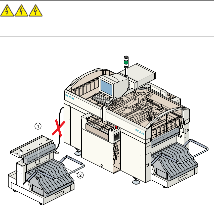
Fig. 5 - 11 Component trolley, transformer T1
(1) Transformer T1
(2) Top part of frame
5
Assembly Instructions, Converting the Power Supply 5 Converting the power supply on S-27 HM machines/ and on component trolleys
12/2013 Edition 5.9 Converting the component trolley from 120 VAC to 230 VAC
209
5.9.1 Converting transformer T1 from 120 VAC to 230 VAC
Transformer T1 (item 1 in Fig. 5 - 11) can be accessed from beneath the top part of the frame
(item 2 in Fig. 5 - 11
). 5
Loosen the four hexagon socket-head screws.
Pull the cover plate over the transformer housing down and off.
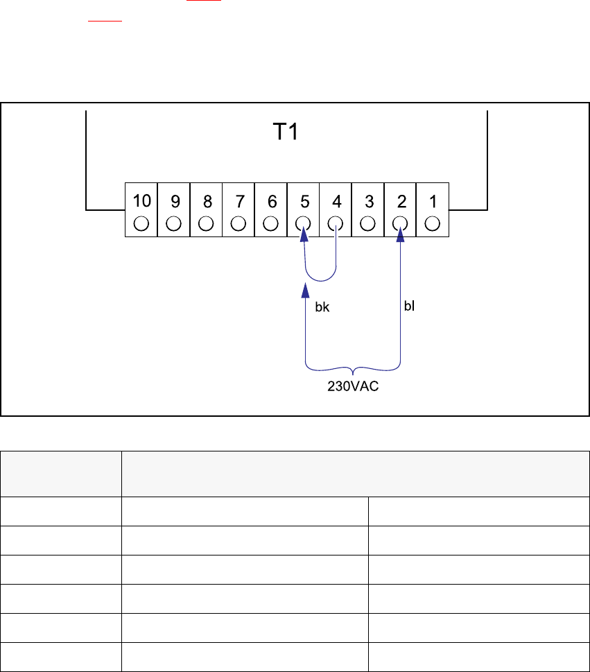
Fig. 5 - 12 Component trolley, transformer T1, terminals
Detach the black wire from terminal 5 and connect to terminal 4.
Voltage
Terminals
Blue wire Black wire
242 VAC 1 5
230 VAC 2 5
219 VAC 3 5
126 VAC 1 4
120 VAC 2 4
114 VAC 3 4
Tab. 5 - 2 Changeover table, supply voltages for transformer T1