00193437-03_AI_PowerSupplyConversion_DE+EN.pdf - 第213页
Assembly Instructions, Converting the Power Supp ly 5 Converti ng the power supply on S-27 HM ma chines/ and on component trolleys 12/2013 Edition 5.9 Converting the component trolley from 120 VAC to 230 VAC 211 5 Fig. 5…

5 Converting the power supply on S-27 HM machines/ and on component trolleys Assembly Instructions, Converting the Power Supply
5.9 Converting the component trolley from 120 VAC to 230 VAC 12/2013 Edition
210
5.9.2 Replacing the fuse
There are two versions of the main power supply for the component trolley: 5
Replacing the fuse F1 on the old power supply 5
Here, the fuse is located on the primary side of transformer T1. The fuse F1 must be replaced (see
circuit diagram 00301239-040301LD4, page 212
) 5
Replace the fuse in the fuse holder in the cover panel:
old rating: 6,3 A T
new rating: 3,15 A T
Replace the adhesive label specifying 6.3 A with the 3.15 A label from the conversion kit.
Replace the cover panel over the transformer and tighten the four hexagon socket-head
screws.
New power supply 5
Here there are two fuses on the secondary side of transformer T1. The fuses do not have to be
replaced (see circuit diagram 00301239-060101LD4, page 213
) 5
Replace the cover panel over the transformer and tighten the four hexagon socket-head
screws.
5.9.3 Checking the protective wire connections
Check that the detached protective earth wires have been reconnected correctly.
5.9.4 Carry out the safety check to DIN EN 60 204
When the conversion is complete, carry out a safety check to DIN EN 60 204.
Follow the procedure described in section 2, page 146 onwards.
5
Assembly Instructions, Converting the Power Supply 5 Converting the power supply on S-27 HM machines/ and on component trolleys
12/2013 Edition 5.9 Converting the component trolley from 120 VAC to 230 VAC
211
5
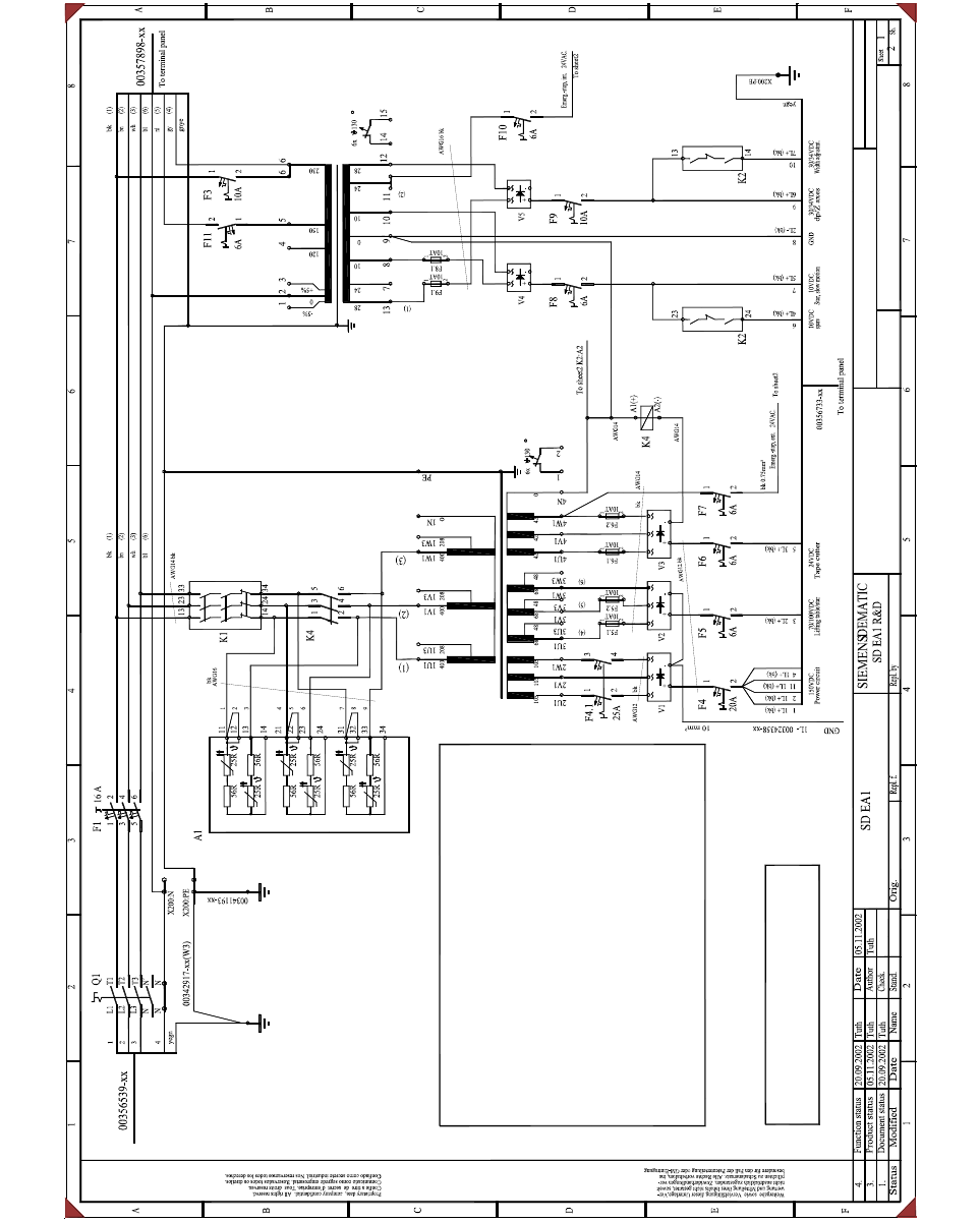
Fig. 5 - 13 S-27 HM circuit diagram
SMD placement system
Siplace S27HM
Power supply circuit diagram
00336812-040301LD3
Power supply base
inrush current limitation
T1
If the machine is operated with 208/120V (USA) please note:
1.) Connect the inrush current limiter A1 in parallel:
Grounding bolt
Front cover
Warning! Main power supply voltage!
If required, root the N conductor
via the main power switch. (IT net)
eg. France / Italy / USA
To the line filter
Main switch
A note regarding the fine-wire fuses !
When any of the F5, F6,
F8 or F9 contactors has tripped, the micro-fuses F5.1, F5.2
or F6.1, F6.2 or F8.1 or F9.1 always
have to be checked.
Drawing: 3 x 400 VAC main power supply voltage
Detach wire 3 from terminal 13 and connect to terminal 14.
Detach wire 2 from terminal 12 and connect to terminal 13.
Detach wire 6 from terminal 23 and connect to terminal 24.
Detach wire 5 from terminal 22 and connect to terminal 23.
Detach wire 9 from terminal 33 and connect to terminal 34.
Detach wire 8 from terminal 32 and connect to terminal 33.
2.) Reconnect the T1 transformer infeed from 230 VAC to 120 VAC.
Detach wire (L) from terminal 6 and connect to terminal 4.
2.) Reconnect the T2 transformer infeed from 3x400 VAC to 3x208 VAC.
Detach wire (1) from terminal 1U1 and connect to terminal 1U3.
Detach wire (2) from terminal 1V1 and connect to terminal 1V3.
Detach wire (3) from terminal 1W1 and connect to terminal 1W3.
T2
(L)
5 Converting the power supply on S-27 HM machines/ and on component trolleys Assembly Instructions, Converting the Power Supply
5.9 Converting the component trolley from 120 VAC to 230 VAC 12/2013 Edition
212
5
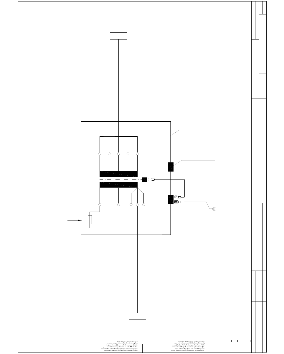
Fig. 5 - 14 Component trolley power supply , old version
bl
gnye
5
4
3
2
1
10
9
7
8
6
28V/3A
8V/2A
0V
8V/2A
28V/3A + 2A 50% ED 1
4
2
3
5230V
115V
+5%
0V
-5%
gnye
F1 = 3.15 AT for 230VAC
F1 = 6.3 AT for 115VAC
Transformer cover
CO table
Ground
DEMATICSIEMENS
00301239-040301LD4
Old version
Interface
To
F1
ModifiedStatus Date
PL EA 1 E2
Orig./Repl.f/Replaced byStand.Name
Check.
Stromlaufplan/Circuit diagram
Author
Date
Siplace SMD placement system
1
1
Transformer, CO trolley
00301069-xx
Cable: Transformer - power supply
Sh.
Sh.
1.5mm²
04.
03.
01.
29.08.00
01.06.01
01.06.01 Tek
Tek
Wa. 11.07.1994
Eschenweck
Document status
Product status
Function status
X21ar
To
Control board
component table
X36
T1
bn
PE
PE
00300379
Cable: CO table power supply
PE
Connection for
grounding cable, CO trolley
Part 001