00193437-03_AI_PowerSupplyConversion_DE+EN.pdf - 第217页
Assembly Instructions, Converting the Power Supp ly 6 Converting the power supply on the MTC 12/2013 Edition 6.3 Modules to be converted 215 6.3 Modules to be co nverted The following table lists those modules that ha ve…

6 Converting the power supply on the MTC Assembly Instructions, Converting the Power Supply
6.1 Tools and equipment 12/2013 Edition
214
6 Converting the power supply on the MTC
This section describes how to convert the power supply unit for the matrix tray changer (MTC) on
the S-27 HM placement machine in order to adapt them to the supply networks in individual coun-
tries. 6
PLEASE NOTE: 6
The conversion can only be carried out if the MTC was supplied with the "USA conversion kit for
MTC" option (item no. 00116437-01). 6
6.1 Tools and equipment
– Set of DIN 911 Allen keys
– Set of slotted-head screwdrivers
– Multimeter
6.2 Parts
The following parts are supplied with the accessory bag: 6
– Jumper, gray, 3 x
item no. 00353338-01
– 5 x 20, T 6.3 A, micro-fuse, 10 x (for 120 VAC component table)
item no. 00806005-01
– 5 x 20, T 3.15 A, micro-fuse, 10 x (for 230 VAC component table)
item no. 00304938-01
Assembly Instructions, Converting the Power Supply 6 Converting the power supply on the MTC
12/2013 Edition 6.3 Modules to be converted
215
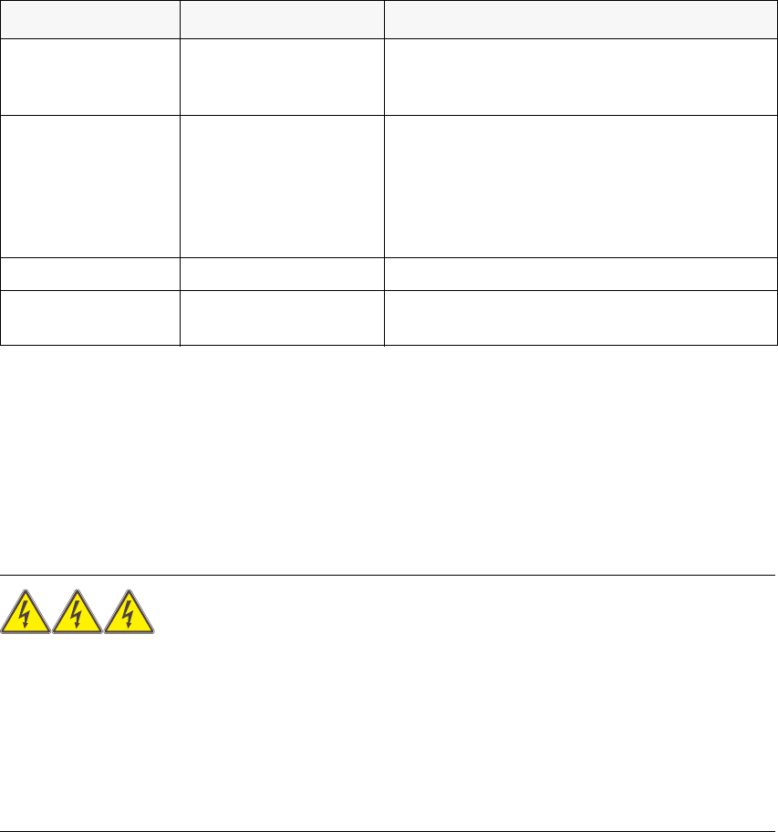
6.3 Modules to be converted
The following table lists those modules that have to be converted in order to adapt them to the
power supply network.
6.4 Converting the power supply from 3 x 400 VAC to 3 x 208 VAC
Dock the MTC out of the placement machine.
RISK OF DEATH 6
Disconnect the MTC from the main power supply.
Remove the plug for the communication cable from the placement machine.
Take suitable action to ensure that the MTC cannot be connected to the power supply during
the conversion work.
Put up warning signs to indicate that work is being carried out on the electrical system.
Module Sub-module Ratings
Electronic panel Terminal panel X01
3 x 400 VAC ± 5%
3 x 208 VAC ± 5%
50 - 60 Hz
Power supply for
component feeder
table
Transformer T1
242 VAC / 50 Hz
230 VAC / 50 Hz
219 VAC / 50 Hz
126 VAC / 50 Hz
120 VAC / 50 Hz
114 VAC / 50 Hz
Fuse F1 3.15 AT at 242 VAC, 230 VAC, and 219 VAC
Adhesive label
3.15 AT at 242 VAC, 230 VAC, and 219 VAC
6.3 AT at 126 VAC, 120 VAC, and 114 VAC
Tab. 6 - 1 Modules to be converted
6 Converting the power supply on the MTC Assembly Instructions, Converting the Power Supply
6.4 Converting the power supply from 3 x 400 VAC to 3 x 208 VAC 12/2013 Edition
216
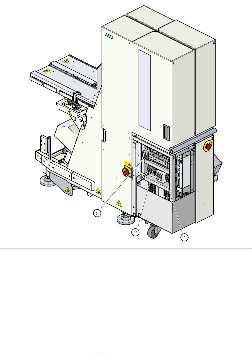
6.4.1 Conversion work on the electronic panel
6
Fig. 6 - 1 Position of the electronic panel
(1) Electronic panel
(2) Terminal block X01
(3) Motor contactor Q01
6
Release the screws for the electronic panel cover.
Lift off the cover.
Remove the three transverse jumpers from feed-through terminals 2-3, 6-7 and 10-11 on ter-
minal block X01 (point 2 in Fig. 6 - 1
).