00193437-03_AI_PowerSupplyConversion_DE+EN.pdf - 第221页
Assembly Instructions, Converting the Power Supp ly 6 Converting the power supply on the MTC 12/2013 Edition 6.4 Converting the power supply from 3 x 400 VAC to 3 x 208 VAC 219 6.4.2 Conversion work on the T1 transformer…
6 Converting the power supply on the MTC Assembly Instructions, Converting the Power Supply
6.4 Converting the power supply from 3 x 400 VAC to 3 x 208 VAC 12/2013 Edition
218
6
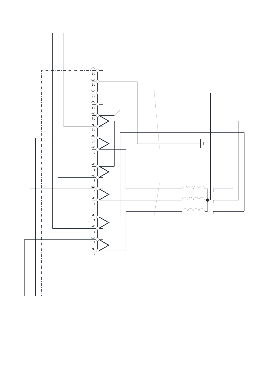
Fig. 6 - 3 MTC2 - terminal panel X01, circuit diagram 3 x 208 VAC
1V1
1 2 3
2U1
2V1
2W1
4x2.5mm² CSA
1W1
1U1
3.7 kVA /50-60Hz
Oilflex 190
-W003
Transformer T1
3 x 208 VAC / 3 x 400 VAC
3 x 208 VAC / 120 VAC
L1
L2
50Hz / 60 Hz
L3
PE
X01 terminal block
5x2.5mm² CSA
1 2 3 4
Oilflex 190
-W004
PE
L3.1
L1.1
L2.1
C
A A
JMPJMP JMPJMP JMPJMPJMP: 3 x 208 VAC
N
Assembly Instructions, Converting the Power Supply 6 Converting the power supply on the MTC
12/2013 Edition 6.4 Converting the power supply from 3 x 400 VAC to 3 x 208 VAC
219
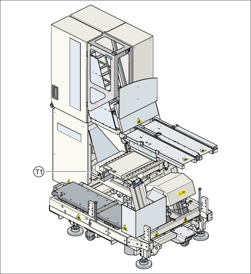
6.4.2 Conversion work on the T1 transformer for the component table
6.4.2.1 Converting transformer T1 from 230 VAC to 120 VAC
– Remove the tape roll container and the waste container.
– Release the screws for the MTC cover on the component table side.
– Lift off the cover.
6
Fig. 6 - 4 Position of transformer T1 for the component table
6
6 Converting the power supply on the MTC Assembly Instructions, Converting the Power Supply
6.4 Converting the power supply from 3 x 400 VAC to 3 x 208 VAC 12/2013 Edition
220
T1 Transformer for the main power supply for communication on the component table 6
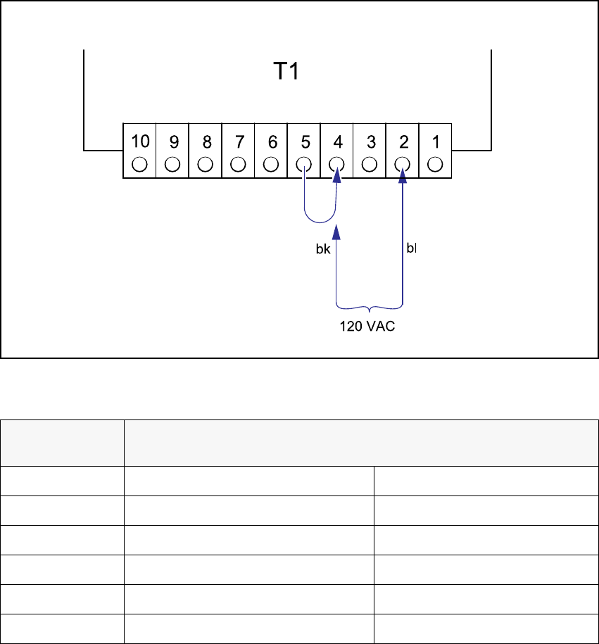
Fig. 6 - 5 Component table, transformer T1, 120 VAC connection
6
6
Detach the black wire from terminal 5 and connect to terminal 4.
Voltage
Terminals
Blue wire Black wire
242 VAC 1 5
230 VAC 2 5
219 VAC 3 5
126 VAC 1 4
120 VAC 2 4
114 VAC 3 4
Tab. 6 - 1 Changeover table, supply voltages for transformer T1