00193437-03_AI_PowerSupplyConversion_DE+EN.pdf - 第226页
6 Converting the power supply on the MTC Assemb ly Instructions, Converting the Power Supply 6.5 Converting the power supply from 3 x 208 VAC to 3 x 400 VAC 12/2013 Edition 224 6 Fig. 6 - 8 MTC - terminal panel X01, circ…
Assembly Instructions, Converting the Power Supply 6 Converting the power supply on the MTC
12/2013 Edition 6.5 Converting the power supply from 3 x 208 VAC to 3 x 400 VAC
223
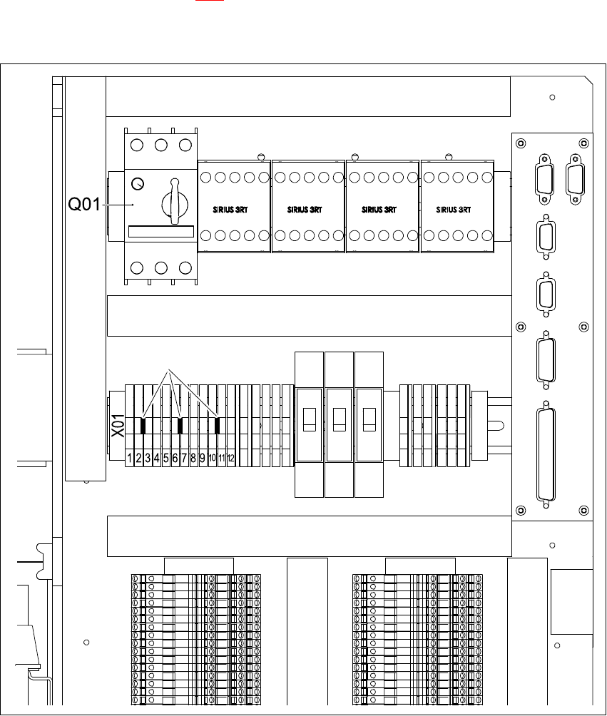
On terminal block X01, plug in three transverse jumpers between feed-through terminals 2-3,
6-7 and 10-11 (BR see Fig. 6 - 7
).
Leave the tripping current setting unchanged at 3.5 A on motor contactor Q01.
6
Fig. 6 - 7 MTC electronic panel - jumper set for 3 x 400 VAC
JMPJumper, 3 x 6
Q01 Motor contactor 6
X01 Terminal block 6
JMP (3 x 400 VAC) 6
6 Converting the power supply on the MTC Assembly Instructions, Converting the Power Supply
6.5 Converting the power supply from 3 x 208 VAC to 3 x 400 VAC 12/2013 Edition
224
6
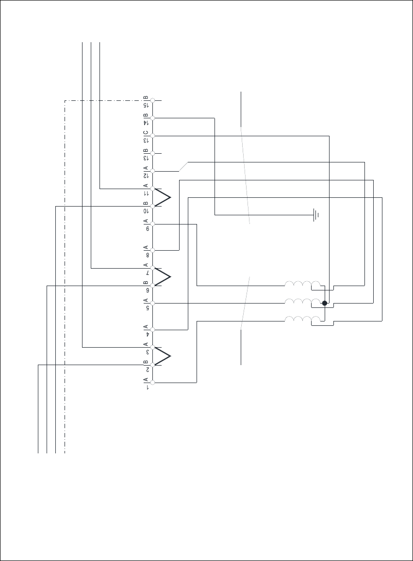
Fig. 6 - 8 MTC - terminal panel X01, circuit diagram 3 x 400 VAC
1V1
1 2 3
2U1
2V1
2W1
4x2.5mm² CSA
1W1
1U1
3.7 kVA /50-60Hz
Oilflex 190
-W002
Transformer T01
3 x 208 VAC / 3 x 400 VAC
3 x 400 VAC / 230 VAC
L1
L2
50Hz / 60 Hz
L3
PE
Terminal panel X01
5x2.5mm² CSA
1 2 3 4
Oilflex 190
-W003
PE
L3.1
L1.1
L2.1
C
A A
JMP
JMP: 3 x 400 VAC
JMP JMP
N
Assembly Instructions, Converting the Power Supply 6 Converting the power supply on the MTC
12/2013 Edition 6.5 Converting the power supply from 3 x 208 VAC to 3 x 400 VAC
225
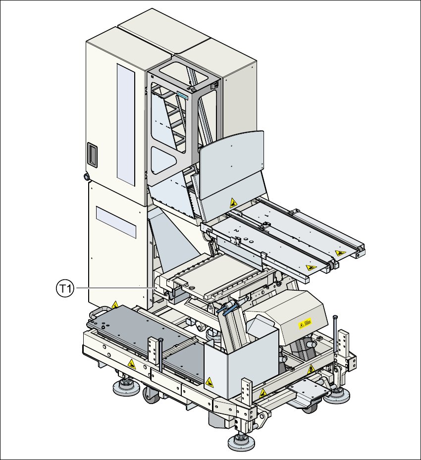
6.5.2 Conversion work on the T1 transformer for the component table
6.5.2.1 Converting transformer T1 from 120 VAC to 230 VAC
– Remove the tape roll container and the waste container.
– Release the screws for the MTC cover on the component table side.
– Lift off the cover.
6
Fig. 6 - 9 Position of transformer T1 for the component table
6