00193437-03_AI_PowerSupplyConversion_DE+EN.pdf - 第253页
Assembly Instructions, Converting the Power Supp ly 7 Conv erting the power supply on the HS-60 / D4 / D1/D2 machine 12/2013 Edition 7.7 HS-60 circuit diagrams 251 7.6.8 Inst alling the power supply unit Carefully push…
7 Converting the power supply on the HS-60 / D4 / D1/D2 machine Assembly Instructions, Converting the Power Supply
7.6 Converting the power supply from 3 x 208 VAC to 3 x 400 VAC 12/2013 Edition
250
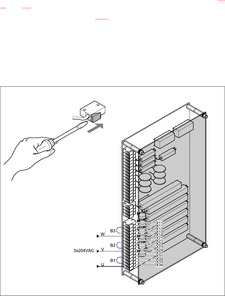
7.6.7 Reconnecting the inrush current limiter board
The inrush current limiter board is located on the back of the front panel (see item EST in Fig. 7 -
18, page 249.
Move the following jumpers (see Fig. 7 - 20):
B3 from terminal X13 to terminal X12
B2 from terminal X23 to terminal X22 and
B1 from terminal X33 to terminal X32.
Reconnect the following wires:
(W) from terminal X14 to terminal X13,
(V) from terminal X24 to terminal X23 and
(U) from terminal X34 to terminal X33.
)
:
Fig. 7 - 20 Reconnecting the inrush current limiter board

Assembly Instructions, Converting the Power Supply 7 Converting the power supply on the HS-60 / D4 / D1/D2 machine
12/2013 Edition 7.7 HS-60 circuit diagrams
251
7.6.8 Installing the power supply unit
Carefully push the power supply unit into the housing until it reaches the stop.
Use the M8 hexagon socket-head screw to secure the unit at the bottom.
Check that the yellow-green PE wire is connected to the door.
Close the door.
PLEASE NOTE: 7
Make sure that the actuating shaft of the main switch slides easily into the opening in the ro-
tary button. 7
Use the machine key to lock the door.
7.6.9 Carry out the safety check to DIN EN 60 204
When the conversion is complete, carry out a safety check to DIN EN 60 204.
Follow the procedure described in section 2, page 146 onwards.
7.7 HS-60 circuit diagrams
3 x 208 VAC conversion kit for SIPLACE HS-60, for USA
00119085-050101LD4, 2 sheets, see page 252
and 253 7
SIPLACE HS-60 conversion kit, international
00119185-050101LD4, 2 sheets, see page 254
and 255 7
7 Converting the power supply on the HS-60 / D4 / D1/D2 machine Assembly Instructions, Converting the Power Supply
7.7 HS-60 circuit diagrams 12/2013 Edition
252
7
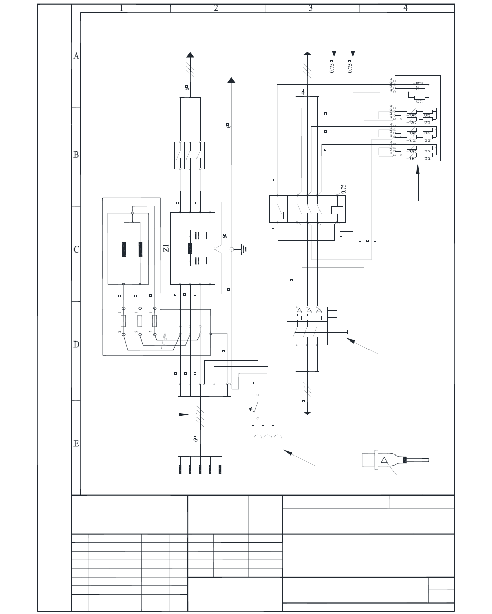
Fig. 7 - 21 HS-60 circuit diagram, 00119085-050101LD4, sheet 1 of 2
11.05.03
5.
1.
1.
Hi
01.10.03 Hi
2
3x208 VAC conversion kit
for SIPLACE HS60 (for the USA)
00119085-050101LD4
Hi
Hi
11.04.02
11.04.02
Weitergabe sowie Vervielfältigung dieser Unterlage, Verwertung und Mitteilung
ihres Inhaltes nicht gestattet, soweit nicht ausdrücklich zugestanden.
Zuwiderhandlungen verpflichten zu Schadenersatz. Alle Rechte für den Fall der
Patenterteilung oder GM-Eintragung vorbehalten.
Copying of this document, and giving it to others and the use or communication
of the contents thereof, are forbidden without express authority. Offenders are
liable to the payment of damages. All rights are reserved in the event of the grant
of a patent or the registration of the utility model or design.
SIEMENS DEMATIC
Function status
Product status
Document status
Scale
Date Name
Stat. Modified Date Name
SD EA 1 R&D
Check.
Author
Stand.
(Material number)
Mat. no. - FS PS DS L/F
Sheet
File name:
Inrush current limiter - transformer
A1(+)
A2(-)
1
3
5
2
4
6
K1.1
2
TransfPrim
(Sheet 2)
Psz1
Nsz1
1.5
1.5
1.5
1.5 1.5 1.5
1
Contactor relay block (NC)
0.750.75
0.75
(Sheet 2)
K1 main contactor
U
V
W
N
PE PE
N
4A
2.5
2.5
2.5
6 bn
6
Three-phase current
Power plug
St1
Service
socket
Bu1
X1
RGP
U
V
W
F1
PE
Line filter
6 bn
6 bn
L1
L2
L3
L1'
L2'
L3'
6 bn
6 bn
6 bn 6 bn
6 bn
6 bn
6 bn
PE
Main switch
S1
1
3
5
2
4
6
Top hat rail 1
(Sheet 1)
HS1
Rack grounding point
To MGP (main grounding point)
MS1
Motor contactor
1
3
5
2
4
6
Discharge reactor
U
V
W
Z2
3
5
1 F1
F3
F5
2
4
6
F1, F3, F5 1AT
Jumper
1.5 bn
1.5 bn
1.5 bn
4
HS1
6
U
V
W
2.5
1
Warning label no. 211
( ! Discharge time )
CEE plug
00345937
Main power cable
for the USA
00342496
Motor protection trip block 32 A
00357871
Socket guard
Reconnected
for the USA
3 x 208 VAC
Insert into service socket