00193437-03_AI_PowerSupplyConversion_DE+EN.pdf - 第264页
8 Converting the power supply on the HS-XX / Di machine using PKE32/XTU-32 Assembly Instructions, Converting the Power Supply 8.5 Converting the power supply from 3 x 400 VAC to 3 x 208 VAC 12/2013 Edition 262 8 Fig. 8 -…
Assembly Instructions, Converting the Power Supply 8 Converting the power supply on the HS-XX / Di machine using PKE32/XTU-32
12/2013 Edition 8.5 Converting the power supply from 3 x 400 VAC to 3 x 208 VAC
261
8.5.2 Replacing the motor circuit-breaker
The PKE32/XTU-32 motor protection switch, item no. 03098183-01, can be used in 3 x 208 VAC
± 5% and 3 x 230 VAC ± 5% supply voltages. The position of the motor protection switch is shown
in Fig. 8 - 2
on page 260, item MS1. 8
– Remove the old complete MS1 & MS1A and replace them with the new MS1 (PKE32/XTU-32).
– This MS1 PKE32/XTU-32 part is backward compatible to the old MS1/MS1A.
– Insert the new MS1 (PKE32/XTU-32) at the same location as the old MS1 position.
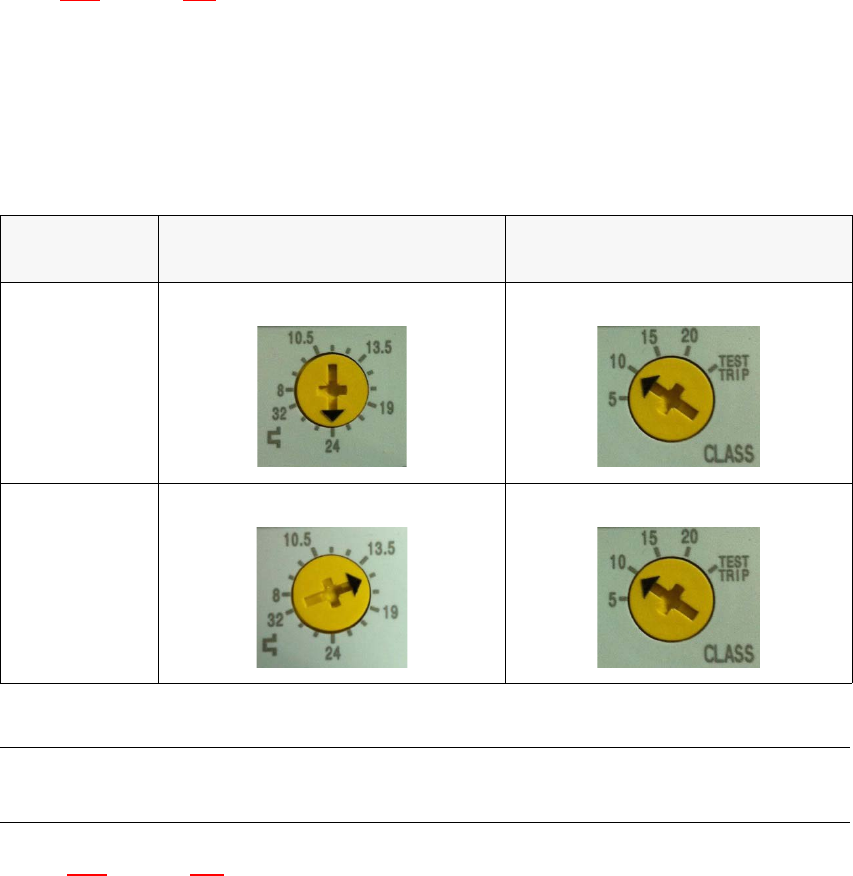
– Set the over current and short circuit trip threshold settings as shown below.
8
Tab. 8 - 2 Overcurrent and short-circuit threshold for 3 x 208 VAC, 3 x 230 VAC
PLEASE NOTE:
On PKE32/XTU-32 the motor protection trip block need not be changed. 8
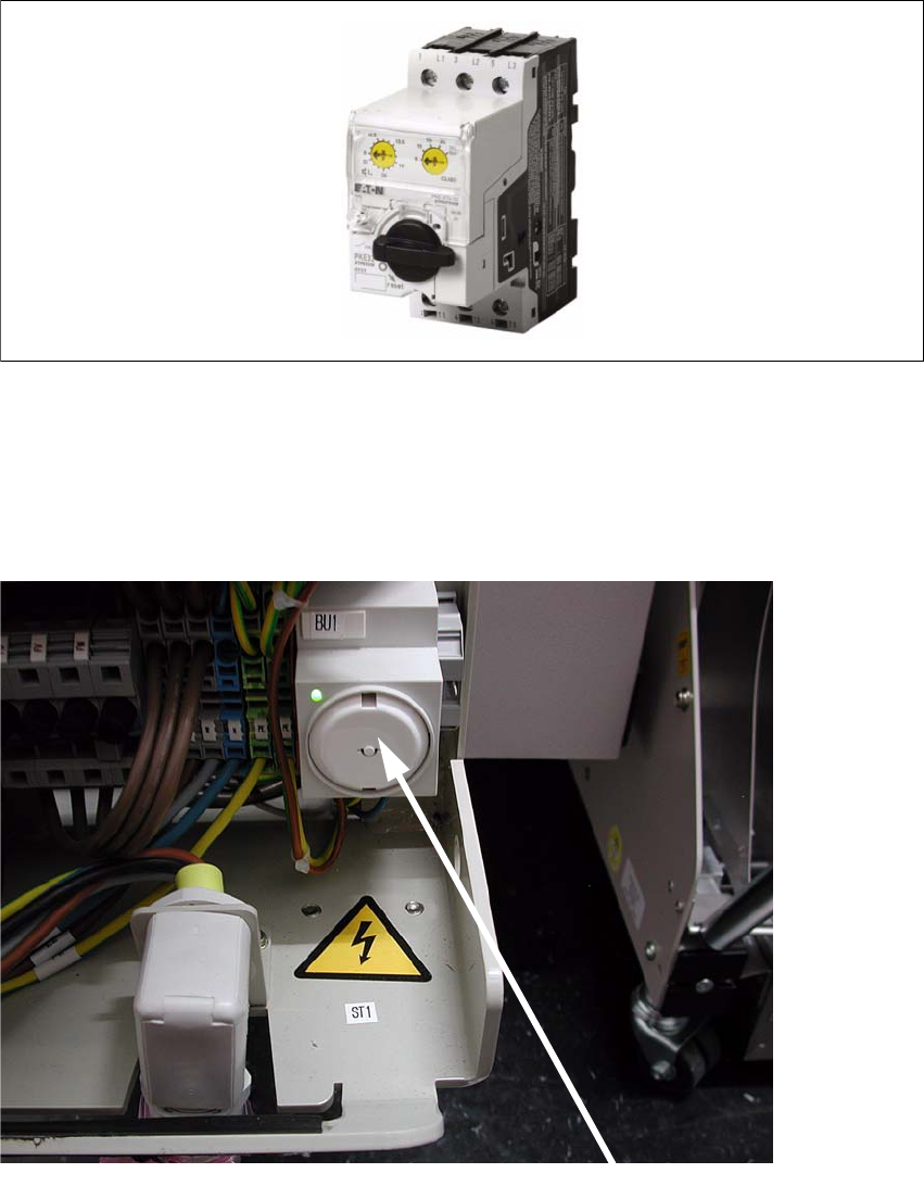
–Fig. 8 - 3
on page 262 shows the PKE32/XTU-32 motor protection switch.
Power supply
Over current trip threshold (left
dial)
Short circuit current trip class
(right dial)
HS-60 / D4
24 A Class 10
D1 / D2
15 A
Class 10
8 Converting the power supply on the HS-XX / Di machine using PKE32/XTU-32 Assembly Instructions, Converting the Power Supply
8.5 Converting the power supply from 3 x 400 VAC to 3 x 208 VAC 12/2013 Edition
262
8
Fig. 8 - 3 PKE32/XTU-32 front side view
8.5.3 Securing the socket with earthing contact using the socket guard
Insert the Teddy socket guard, series 6310, white (item no.: 00357871-01) into the socket
guard with earthing contact.
8
Socket with socket guard

Assembly Instructions, Converting the Power Supply 8 Converting the power supply on the HS-XX / Di machine using PKE32/XTU-32
12/2013 Edition 8.5 Converting the power supply from 3 x 400 VAC to 3 x 208 VAC
263
8.5.4 Replacing the main power cable
CAUTION
The electrical cables to each individual placement machine must be clearly identified and easy to
allocate without doubt. The regulations of the country in which the machine is operated apply.
The main power cable is connected to the U, V, W, N and PE terminals on terminal strip X1 (see
item X1 in Fig 8 - 2
, page 260).
Detach the wires of the main power cable from the U, V, W, N and PE terminals.
Detach the cable clamp from the cable holder.
Pull the cable out of the cable holder.
Push the main power cable (6 mm²) through the cable holder as far as the terminals on X1.
PLEASE NOTE: 8
Make sure that the cable bending radius is sufficient to prevent the wires being bent. 8
Connect the main power cable to the terminals on X1:
Wire 1 to U on X1,
Wire 2 to V on X1,
Wire 3 to W on X1,
Wire 4 to N on X1 and
Wire YEGN to PE on X1.
(See circuit diagram 00119801-010102LD4, sheet 1, page 275
)
Tighten the cable clamp.